
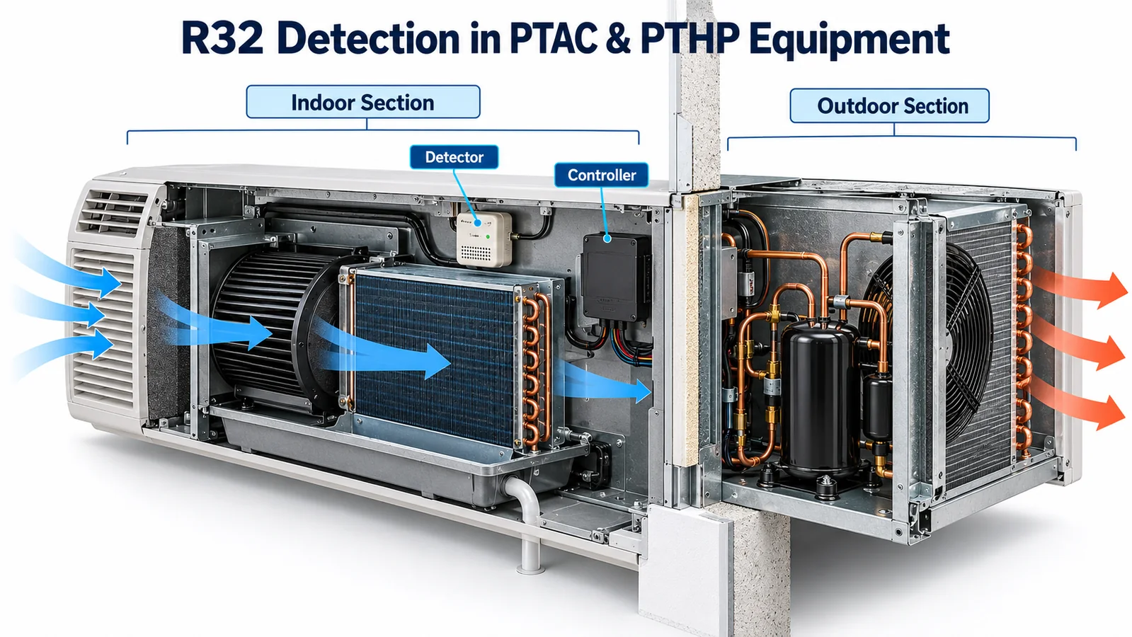
Packaged terminal air conditioners and heat pumps look simple from the occupied room: one chassis, one sleeve, one grille and one controller. For an R32 detection design, however, the unit is not one well-mixed volume. It is a set of connected but unequal spaces. The room-side evaporator section, blower inlet, drain pan, compressor bay, condenser section, wall sleeve and occupied room exchange gas differently as fans, dampers, doors and condensate conditions change.
That architecture makes an R32 leak sensor PTAC project a system-integration task. The detector cannot compensate for an unexamined release path, a blocked inlet, a service panel that moves the harness, or control logic that commands an action without confirming it. The right engineering question is not “How low should the sensor be?” It is “Which credible release must be detected, in which unit configuration and operating state, soon enough for the released mitigation sequence to achieve its intended result?”
This guide presents a practical method for OEM teams. It is not a substitute for the applicable equipment requirements, certification program, controlled refrigerant data, or the instructions for a released PTAC/PTHP model. Values and actions must be selected and verified by the equipment manufacturer for the target market.
1. Begin With the PTAC Safety Function, Not a Convenient Bracket
A useful design brief defines the complete function before the mechanical team freezes a sensor location. Record the refrigerant and maximum charge for each configuration, occupied-space assumptions, unit orientations, sleeve options, airflow modes, heat options, field-installed accessories, controller authority, required annunciation and intended recovery behavior. Identify the controlled requirements and test methods that govern the product. These inputs prevent a sensor from becoming a late component added wherever space remains.
The functional chain is longer than the detector. A release occurs at a joint or component. Refrigerant travels through a cabinet under gravity, momentum, buoyancy, fan pressure and leakage. Gas reaches the sensor inlet. The sensing element and electronics produce a valid output. The controller interprets the output, prioritizes it over normal comfort operation and commands mitigation. Relays, fans, valves or other actuators change physical state. The equipment then remains in or recovers from that state according to a controlled rule.
Every link needs an owner and evidence. The sensor supplier can characterize its module under defined exposure conditions. The PTAC manufacturer must establish whether the installed system detects representative releases and whether the resulting equipment action is effective. A component choice alone does not establish equipment compliance.
2. Map Refrigerant Inventory and Credible Release Sources
Create a refrigerant schematic overlaid on the physical chassis. Include the evaporator, condenser, compressor, reversing valve for heat-pump versions, capillary tube or expansion device, distributors, return bends, headers, service ports, charging stubs, brazed joints and any field-connected items. Mark which components sit on the room side of the air seal and which sit in the outdoor section. Do not assume the factory partition is gas-tight unless its seams, wire penetrations, drain openings and assembly tolerances support that assumption.
The purpose is not to claim that every point has equal leak probability. It is to ensure that a location decision is tested against credible sources, including sources on both sides of a bulkhead. A high-pressure-side discharge joint may release with different momentum and phase behavior than a low-side return bend. A leak can impinge on sheet metal, follow a tube, enter insulation, or split between compartments. These initial conditions can dominate the first seconds of transport.
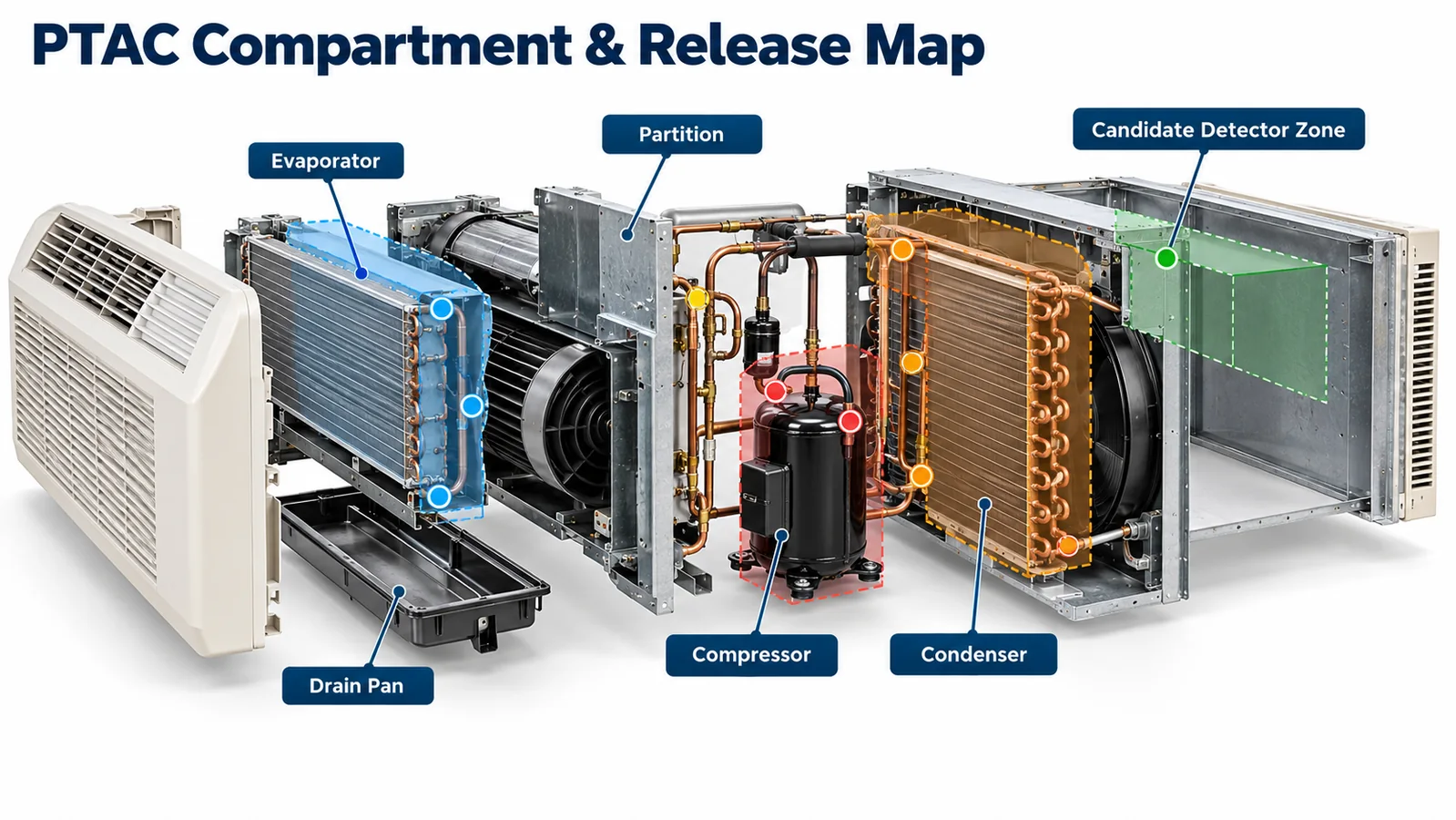
Use the map to propose release points for analysis and testing. Keep the set traceable to the released refrigerant circuit and assembly process. When a supplier, tube route or chassis revision changes, the map becomes a change-control artifact instead of an illustration forgotten after concept review.
3. Treat Room-Side and Outdoor-Side Sections as Different Gas Volumes
The evaporator/blower section normally exchanges air with the occupied room. The condenser/compressor section normally exchanges air outdoors. Between them are partitions that may contain openings for tubing, wires, shafts, drains and structural features. A PTAC can therefore behave as two volumes, several small pockets, or one leaky system depending on pressure and fan state.
Start with three questions for each release source:
- Which volume receives the first significant refrigerant mass?
- What openings allow that volume to communicate with the detector?
- What operating condition creates the slowest or least direct transport?
A sensor in the indoor return path may respond well to an evaporator leak when the indoor blower runs, yet have little coverage for a compressor-bay release that is swept outside by the condenser fan. That may be acceptable if the safety analysis excludes or separately addresses outdoor-dispersed releases. It is not acceptable to call the position universal without documenting the boundary.
Conversely, gaps around tubing or a poorly sealed partition can carry gas toward the room. The engineering team should quantify or test those paths rather than treating the words “outdoor section” as proof of outdoor dispersion. Cabinet pressure measurements, smoke visualization and tracer tests can help identify paths before refrigerant release testing.
4. Evaluate Every Fan and Damper State That Changes Transport
PTAC airflow is state-dependent. At minimum, examine unit off, standby, indoor fan only, compressor cooling, compressor heating, condenser fan operation, defrost or transient modes for PTHP products, fan cycling, continuous-fan settings and abnormal fan failure. Include any fresh-air damper or motorized vent position offered by the product.
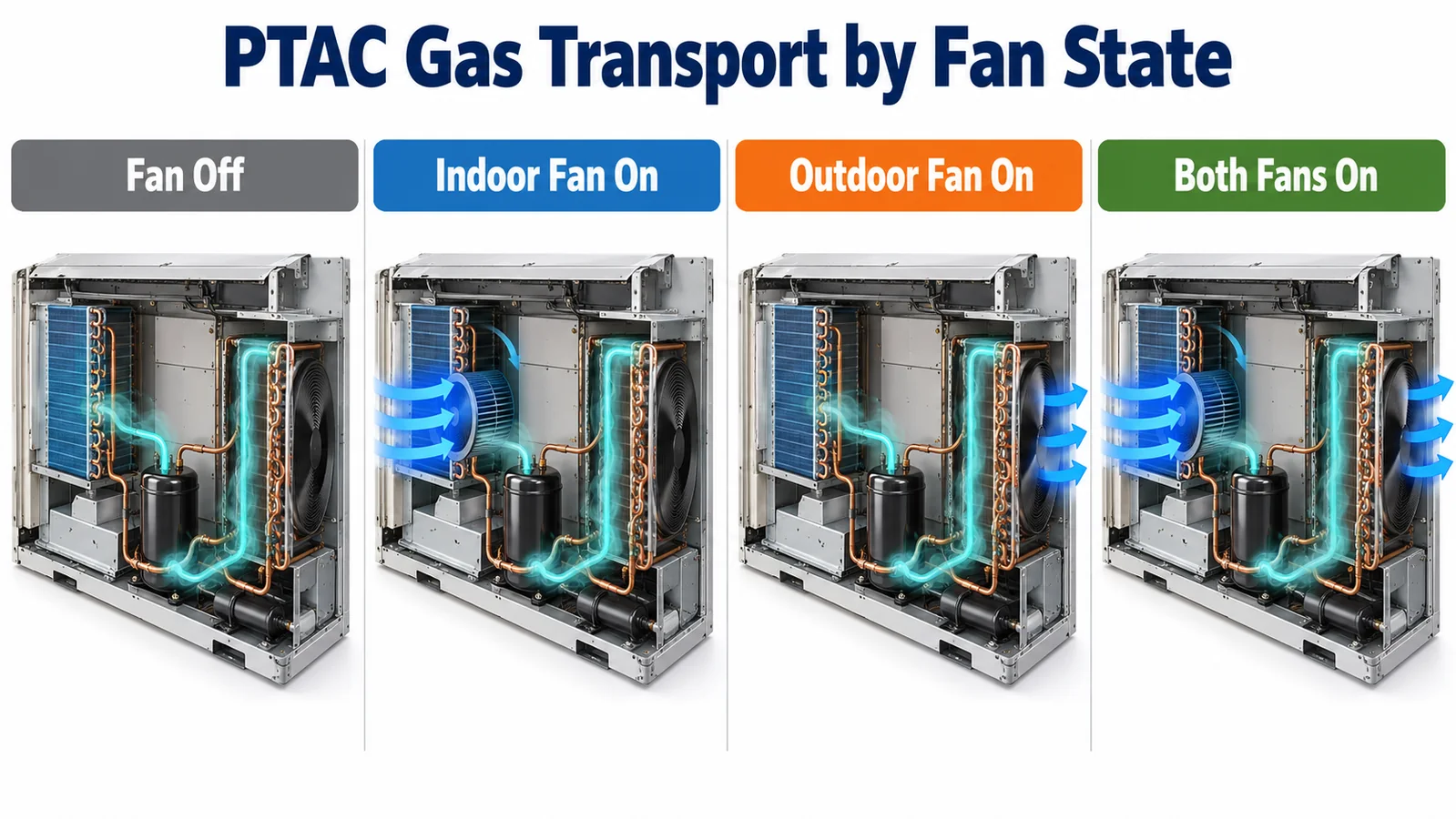
Fan-off cases matter because gas may migrate slowly and collect in a low pocket rather than following the normal airstream. Fan-on cases matter because a release may be rapidly entrained, diluted, pushed through the supply grille or bypass the sensing inlet. A sensor placed in a strong jet may receive a lower local concentration than one in a representative mixed return zone. A sensor hidden behind a baffle may respond during fan-off accumulation but be isolated during forced flow.
Do not reduce this evaluation to a single computational picture. Use calculations or CFD to rank cases and understand mechanisms, then verify limiting cases on hardware. Model assumptions about leakage, turbulence, refrigerant phase and fan curves can be uncertain. The production-intent chassis provides the final geometry, surface temperature and leakage paths that determine actual response.
5. Understand the Wall Sleeve and Occupied-Room Boundary
The wall sleeve is part of the gas-transport system. Clearances around the chassis, seals, louvers, weather barriers, architectural sleeves and field workmanship can create paths that are absent from a bench unit. Wind pressure on the building façade can also drive air through openings even when both fans are off.
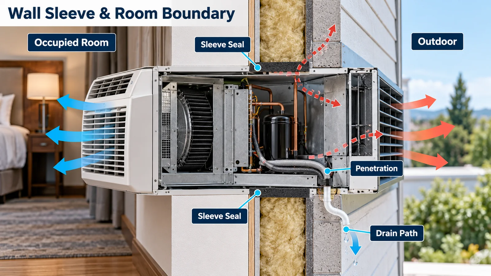
Define representative installation conditions for validation. These may include approved sleeve models, minimum and maximum chassis insertion, specified seals, wall thickness range, outdoor louver configuration and allowable field penetrations. Inspect how power cords, condensate drains, remote thermostat cables and control wiring cross the boundary. A field-installed opening should not silently defeat the transport behavior used during qualification.
The occupied-space interface deserves explicit treatment. Identify paths through the return grille, supply grille, control panel, side gaps and sleeve trim. If mitigation relies on the indoor blower to disperse gas, verify the delivered airflow with the released grille, filter, fan setting and static condition. If a zoning or room-control function can close a path, include that state. The result should be an installation envelope the instructions can reproduce, not a laboratory-only arrangement.
6. Locate the Sensor From Exposure Evidence
Candidate locations should be evaluated against several requirements at once:
- representative access to gas from the covered release sources;
- acceptable response in fan-on and fan-off states;
- separation from direct condensate, splash and cleaning spray;
- operation within the detector’s controlled temperature, humidity and vibration envelope;
- an inlet that is not blocked by foam, wiring, labels, dust screens or service parts;
- sufficient clearance for connector engagement and removal;
- protection from accidental contact without creating a stagnant enclosure;
- repeatable installation across chassis tolerances and allowed orientations.
“Low” is not a complete location definition. A low corner behind an upturned flange may be a dead pocket disconnected from a leak. A position slightly higher in a proven transport path may respond more reliably. Density information informs the hypothesis, but release momentum, surfaces, heat, fans and barriers determine the local concentration-time history.
Document each candidate with coordinates or datums, inlet orientation, surrounding clearances and harness route. Photograph or scan the production-intent installation. Then measure concentration or system response for representative releases. Select the location from the total evidence rather than from one favorable trial.
7. Protect Against Condensate Without Hiding the Inlet
The indoor coil and drain pan create a wet environment. Drain blockage, unit tilt, splash from the blower, sweating tubes and cleaning procedures can expose nearby electronics. PTHP heating and defrost transitions may add temperature cycling and transient moisture.
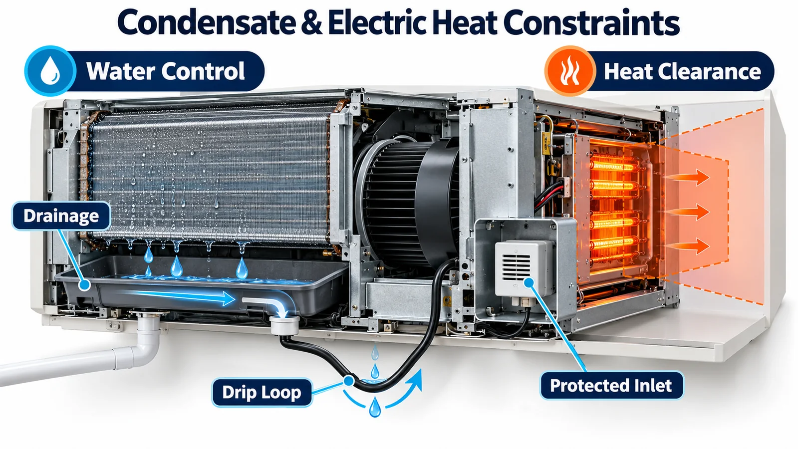
Use gravity and drainage first. Place the detector away from known drip lines, provide cable drip loops, avoid upward-facing pockets and keep the connector out of standing water. A shield can intercept droplets, but its geometry must allow free gas exchange and resist dust accumulation. Verify that the shield does not produce a delayed pocket under the limiting release direction.
Condensation is different from liquid splash. If the detector or its enclosure can fall below local dew point, moisture may form on surfaces even without a direct drip. Examine cold-soak, startup, humid-room and rapid-mode-change cases. Environmental protection claimed for a bare module should not be assumed after it is integrated behind a cover or next to cold metal. Test the installed configuration.
Cleaning exposure also matters. Service personnel may use coil cleaner, disinfectant, aerosol or water near the evaporator. Instructions should protect the sensor inlet and connector during approved cleaning while ensuring temporary covers are removed before return to service. Evaluate credible vapors for cross-response or recovery using the supplier’s guidance and the OEM’s chemical list.
8. Keep Electric Heat and Ignition Sources in the System Analysis
PTHP and cooling-only PTAC platforms may include electric resistance heaters, power relays, motors, electronic air cleaners or other energized parts. The detection and mitigation design must consider how these items are controlled when a valid alarm occurs. A detector positioned near a heater can also experience temperature gradients outside the conditions represented by a room-temperature bench evaluation.
Separate two questions. First, can the sensor perform and survive in the local thermal and electrical environment? Second, does the controller remove or manage potential ignition sources as required by the released safety design? The answer may depend on mode, contactor architecture, residual heat, fan operation and feedback availability.
Do not assume that opening one command signal removes all energy. Map power paths and stuck-relay cases. Where the safety design depends on a contactor or fan, decide whether auxiliary feedback, current sensing, speed feedback or another diagnostic is needed. The exact action sequence belongs to the applicable equipment requirements and certification design; it should not be improvised from a generic article.
9. Design Alarm, Fault and Validity States Explicitly
The controller should distinguish at least startup/warm-up, valid normal data, valid refrigerant alarm, detector diagnostic fault, communication fault, invalid or stale data, power loss and mitigation-device fault. A zero value during warm-up must not be interpreted as proof of clean air. An unchanged data word should not be accepted forever if communication has frozen.
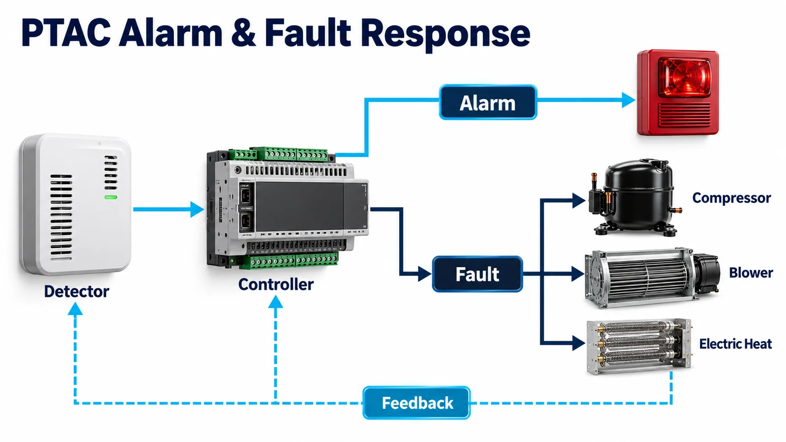
Specify the interface contract for the exact detector variant: supply tolerance, startup timing, validity indication, update rate, data format, alarm semantics, fault codes, timeout, checksum or plausibility checks, electrical levels and recovery behavior. If a hardware alarm output and a serial concentration value both exist, define which is authoritative and how disagreement is handled.
Control priorities must override normal comfort requests when the released safety logic requires it. The sequence should define compressor state, indoor blower state, outdoor fan state, electric heat state, ventilation or damper state, annunciation, latching and service reset. It should also define actuator feedback and the response to failed mitigation. A command log without evidence of physical action is incomplete.
10. Engineer the Harness and Service Interface
PTAC chassis are removed from sleeves for service. Panels open near sharp sheet metal, moving blowers and hot parts. A detector harness can be pulled, pinched, misrouted or left disconnected. Place strain relief so panel motion is carried by the structure rather than the connector. Protect the cable from abrasion and maintain bend radius. Use keyed connectors and clear part identification where different refrigerant variants or outputs could physically fit.
Make the correct post-service configuration obvious. If the sensor must stay in a specific orientation, use an asymmetric bracket or locator. If a temporary protective cap is used during cleaning, add a visible removal step. If detector replacement requires configuration or calibration data, make that workflow controlled and traceable.
The service manual should include a visual inspection, connector check, diagnostic check and a functional verification appropriate to the released design. An electronic self-test may confirm internal electronics but not necessarily gas transport, a blocked inlet, a loose bracket or the entire actuator path. State what each check proves.
11. Select a Detector Conservatively
Winsen lists the ZRT510 R32 module as an NDIR refrigerant sensor intended for OEM integration. The exact module variant, interface, power requirements, dimensions, environmental limits, output behavior, response characteristics and qualification evidence must be taken from the current controlled datasheet and protocol document supplied for the project. Marketing-page values or a shared product image should not replace controlled engineering documents.

An NDIR principle can support refrigerant-specific measurement, but the integration still needs gas-specific calibration, correct variant control, representative exposure and controller diagnostics. Before design freeze, request the model code, revision, refrigerant calibration, output definition, startup behavior, fault behavior, environmental specifications, lifetime/drift evidence, material restrictions, change-notification process and any certification documents relevant to the target market.
The detector is one element in the equipment RDS. The PTAC manufacturer remains responsible for the installed location, release coverage, control sequence, production consistency, instructions and equipment-level evaluation.
12. Build a Production-Intent Validation Matrix
A useful matrix varies the factors that can change gas arrival or mitigation. Include, as applicable:
| Factor | Representative levels |
|---|---|
| Release point | evaporator joints, distributor/return bends, compressor-side joints, service features |
| Operating state | off, standby, fan only, cooling, heating, transient/defrost-related state |
| Fan condition | commanded speeds, cycling, failed or obstructed condition relevant to analysis |
| Sleeve/install | approved sleeves, seal extremes, insertion position, wall and louver configurations |
| Ambiente | temperature and humidity limits, wind condition, wet/dry drain pan |
| Chassis | dimensional extremes, production panels, filter and grille |
| Detector | production revisions and relevant tolerance/aging samples |
| Faults | disconnected sensor, stale communication, bad data, actuator failure, power interruption |
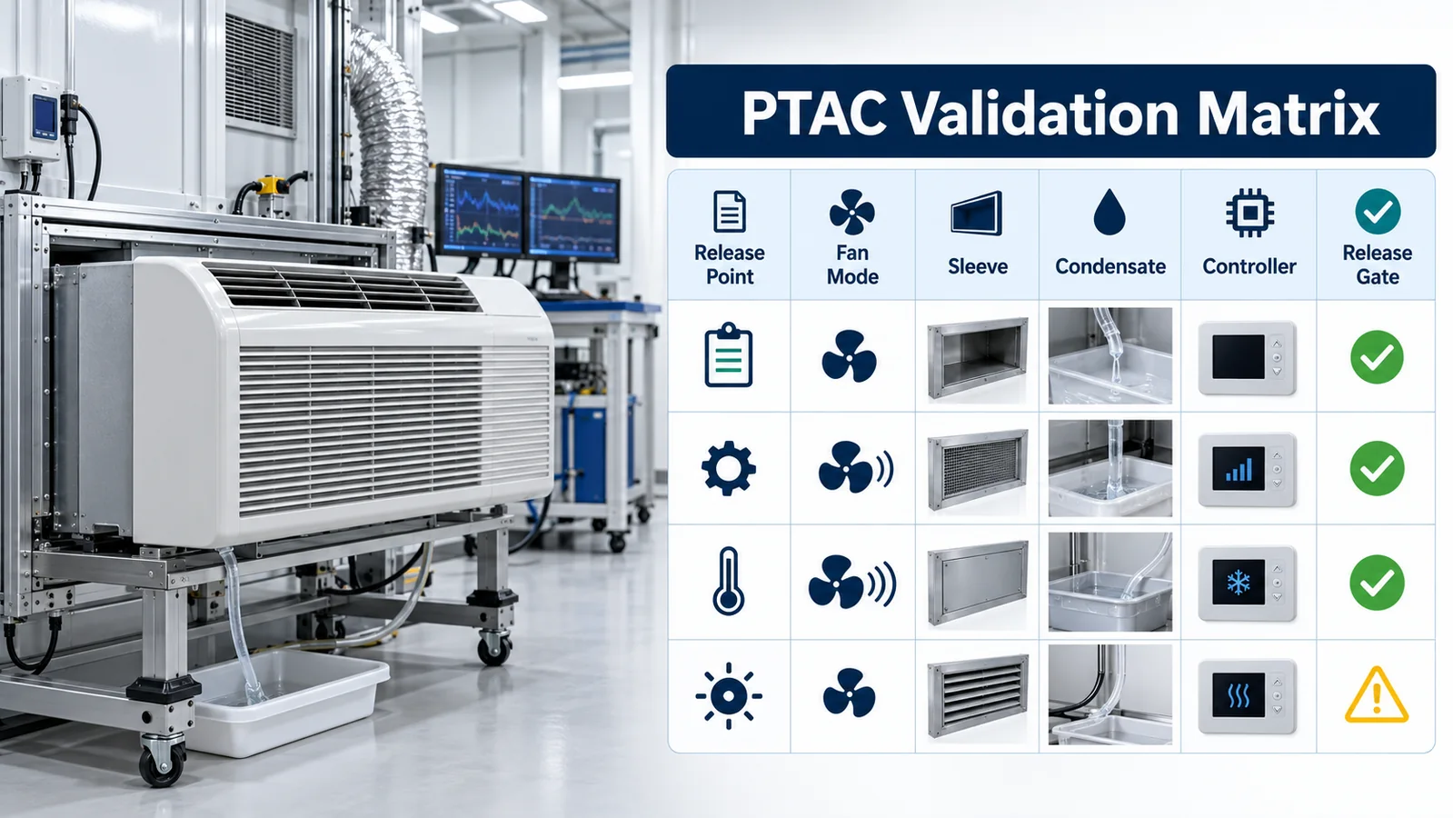
Define objective acceptance criteria before testing. Record release method, mass flow or charge basis, refrigerant condition, instrumentation locations, detector output, controller timestamps, actuator feedback and final system state. Video and synchronized data help explain a pass or failure. Repeat limiting cases to distinguish a stable design from a favorable single trial.
Testing should use production-intent brackets, harnesses, firmware, panels, seals and accessories. A detector taped temporarily into an open chassis can be useful for exploration but does not qualify the released construction. Preserve the worst-case rationale and configuration identifiers in the design record.
13. Control Manufacturing and Field Variation
The qualified position must survive production. Add datums, fixtures, torque or retention controls, harness clips, connector verification and inlet-clearance checks to the work instructions. Prevent insulation, foam, labels or sealant from encroaching on the gas path. Where a sensor variant is refrigerant-specific, use part-number control, barcode or electronic configuration checks to prevent substitution.
End-of-line testing should be proportional to what manufacturing can disturb. Electrical communication and diagnostics can verify connection and configuration. A targeted functional exposure or system check may be required by the released control plan. A self-test alone cannot reveal every blocked-inlet or wrong-location error. Define audit tests that preserve confidence in mechanical exposure.
Field instructions must match the configurations actually evaluated. If orientation, sleeve, grille, accessory or service replacement changes the location, give unambiguous steps and images. UL Solutions emphasizes reviewing the equipment manufacturer’s instructions for the specified sensor location and mitigation behavior. Installation freedom not covered by evidence should not be implied.
14. Use an Engineering Release Checklist
Before releasing an R32 PTAC/PTHP detection design, confirm that the team can answer each item with controlled evidence:
- The refrigerant, charge configurations and applicable equipment requirements are defined.
- Credible release points are mapped to physical compartments and transport paths.
- Fan-off, fan-on, ventilation, heating and relevant transition states are covered.
- Wall sleeve, seals, penetrations, grille, filter and installation tolerances are represented.
- The sensor inlet remains exposed while protected from condensate, splash, debris and service chemicals.
- Thermal, vibration, EMC, power and environmental conditions are inside the released envelope.
- Startup, normal, alarm, fault, timeout and stale-data behavior are specified.
- Commands to compressor, blower, heat and other mitigation devices are verified with appropriate feedback.
- Service removal and replacement cannot easily change orientation, variant, routing or inlet clearance.
- The validation matrix identifies and repeats the limiting configuration.
- Manufacturing checks preserve location, connection, configuration and gas access.
- Product claims and certification statements are supported by current controlled evidence.
If one of these answers is “assumed,” the project has identified useful work before qualification rather than a paperwork gap after failure.
15. Review the Design as a Cross-Functional System
The final location review should include refrigerant-circuit, airflow, mechanical, electrical, embedded-controls, safety/compliance, manufacturing, supplier-quality and service representatives. Each discipline sees a different failure mode. The airflow engineer may identify a bypass jet; manufacturing may know that insulation often shifts; service may show that a panel cannot close without moving the harness; controls may discover that an actuator has no usable feedback. Reviewing the detector only within one subsystem hides these interfaces.
Use a physical unit during the review. Trace the circuit, point to release locations, open every relevant panel and demonstrate the control states. Compare the actual construction with the drawings and validation configuration. Record decisions as requirements or test actions with owners. A photograph of the accepted inlet clearance and harness route is often more useful on the line than a long meeting note.
Also review foreseeable product evolution. A new grille, alternate fan, revised heat kit, different sleeve, regional power option or supplier change may affect transport or response without changing the marketing model. Define triggers for re-analysis and regression testing. Change control should ask whether the modification alters refrigerant inventory, release source, compartment leakage, airflow, sensor environment, interface timing or mitigation authority.
Finally, preserve margins. A design that passes only with a new detector, nominal cabinet and ideal airflow has little resilience to manufacturing tolerance and service aging. Use the validation data to understand distance from the acceptance boundary. Where margin is thin, improve location, gas access, control timing or mechanical repeatability before relying on inspection to hold a fragile result.
Conclusione
Effective R32 leak detection in a packaged terminal air conditioner comes from matching the detector to the actual PTAC architecture. The room-side and outdoor-side compartments, sleeve leakage, fan states, condensate, heat options, service motion and controller authority all shape the result. A good design traces the complete chain from credible release to verified physical mitigation and preserves that chain through production and field service.
For a technical review, provide the refrigerant and maximum charge, PTAC/PTHP configuration, sleeve and orientation, refrigerant-circuit drawing, candidate sensor locations, airflow modes, controller interface, intended alarm and fault actions, environmental limits, annual volume and target certification market. That information allows a sensor supplier and equipment team to discuss the correct detector variant without pretending that a module alone determines system safety.
Riferimenti
- UL Solutions — Inspecting Refrigerant Detection Systems in HVAC Equipment
- UL Solutions — Updated Requirements for Refrigerant Detection Systems
- UL Solutions — Sensor Response in HVAC Systems
- AHRI — Flammable Refrigerants Research Initiative
- AHRTI 9009 — Leak Detection of A2L Refrigerants in HVACR Equipment
- Winsen — ZRT510 R32 Refrigerant Sensor Module
