
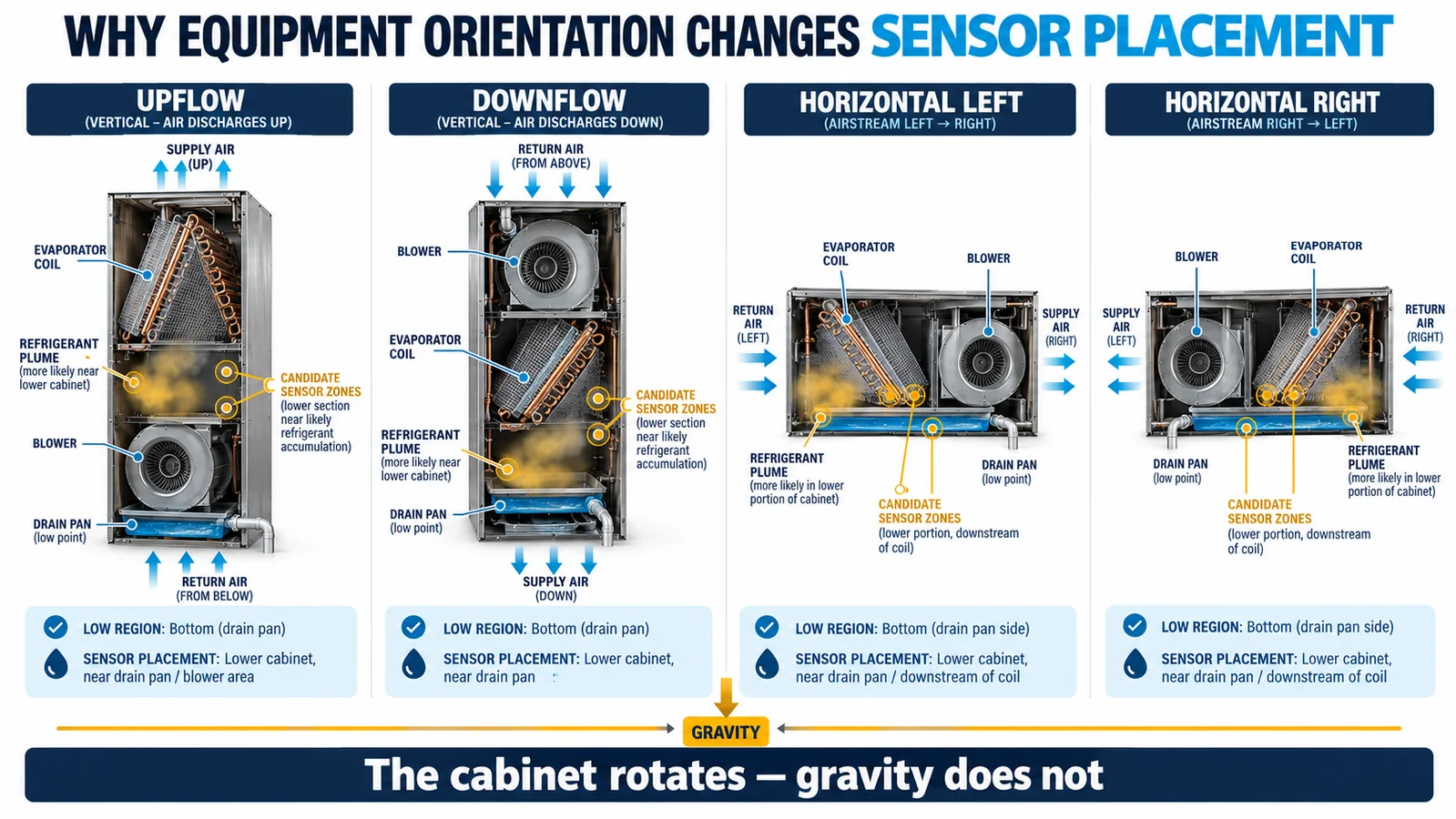
Equipment orientation changes the three-dimensional concentration field that a refrigerant sensor must sample. When a convertible indoor unit moves from upflow to downflow or horizontal installation, the cabinet coordinates rotate but gravity does not. The coil, pan, blower, partitions, harnesses and service panels then form different low regions, pockets and transport paths.
That is why a sensor position should be tied to an approved equipment configuration and validation record. A location that responds early and repeatably in one orientation can be slow, wet, obstructed or bypassed in another. This engineering explainer focuses on the physics and change-control decisions behind that result for R32 and R454B HVAC equipment.
Cabinet coordinates are not world coordinates
A drawing often locates a sensor from a cabinet edge: a distance from the base, side panel or coil rail. That definition is useful for manufacturing but incomplete for functional placement. After rotation, the same coordinate may be above rather than below a leak source, or on a side that no longer receives the plume.
Define the functional location from stable physical references: gravity-relative low region, refrigerant-bearing features, fan side, pan edge, intended gas route and water envelope. Then translate that definition into a controlled bracket and coordinate for each approved orientation.

The initial release is a moving jet
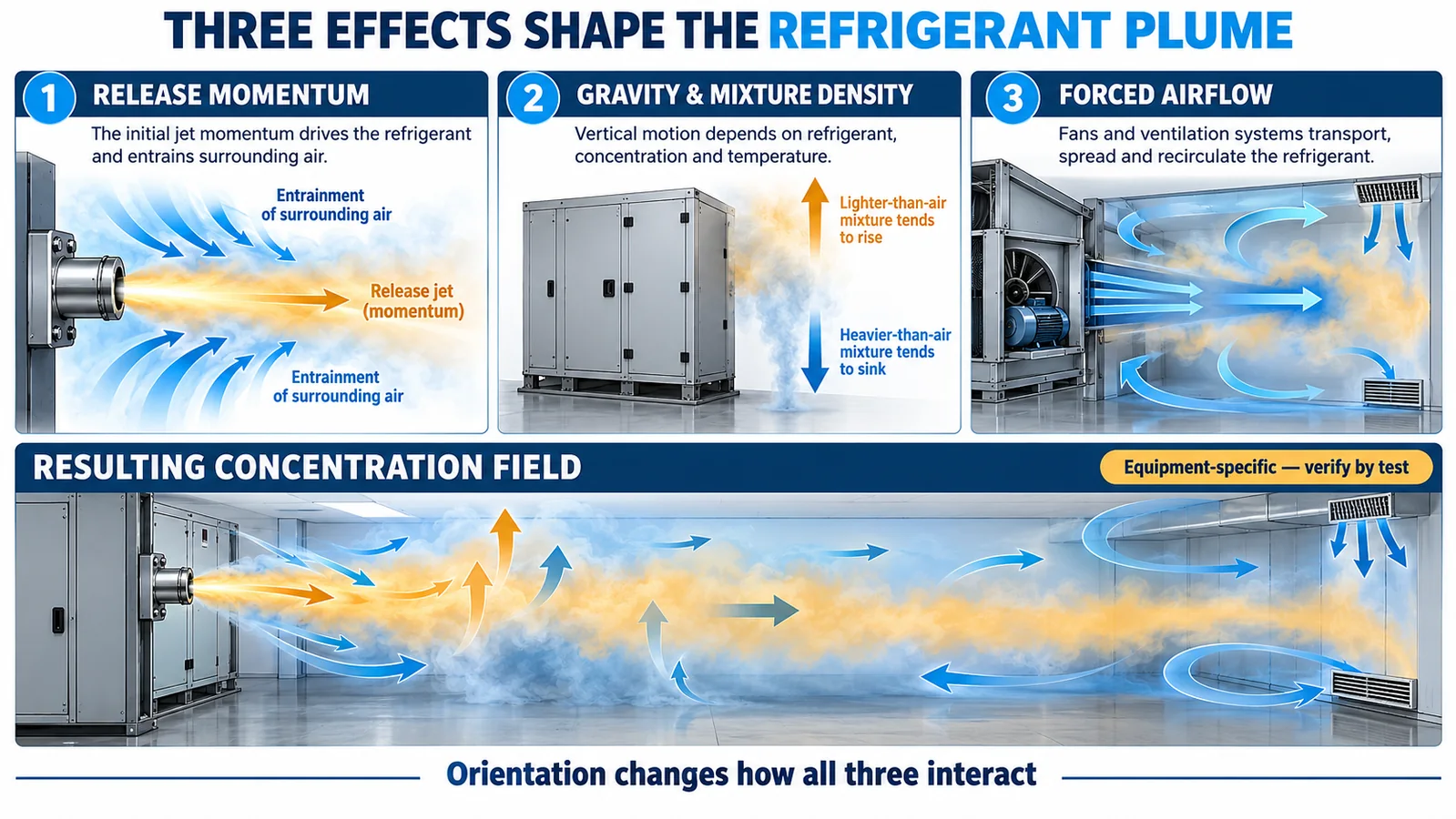
Refrigerant leaving a pressurized circuit begins with momentum. The jet direction, restriction geometry, pressure and impingement on nearby surfaces influence the first path. It also entrains surrounding air and can cool the local mixture. A sensor placed only from a static “heavy gas goes down” assumption may miss this early transport.
Map credible leak sources and directions, including field joints and production connections. Use conservative release cases from the equipment safety analysis and applicable test method. The purpose is not to predict one perfect plume, but to identify candidate positions that can be tested against the range of credible behavior.
Gravity and mixture density act after mixing begins
Molecular weight is one input to buoyancy, not a complete placement rule. The local mixture includes refrigerant and air at changing concentration and temperature. A cold release, warm cabinet surfaces, evaporation, entrainment and heat from operating components can alter vertical motion. R32 and R454B should each be evaluated with the applicable equipment charge and release cases.
Use gravity to identify likely accumulation regions and shadow zones, then verify them. Avoid turning a general property into a universal installation height. The required detector response is an equipment result, not a free-air density demonstration.
Forced airflow can dominate the concentration field
When the blower runs, gas can be transported through the coil, around a bypass gap or out of the cabinet before it reaches a nominal low point. When the blower stops, the same cabinet can form stagnant pockets. Startup and coast-down create additional transient fields.
Qualification should include every fan state that can exist during a credible release and during mitigation. Record commanded and actual airflow where possible. Filters, dampers, heat kits, cabinet leakage and service-panel fit can change local velocity enough to reorder candidate sensor positions.
Internal geometry creates pockets and bypasses
Pan lips, baffles, coil frames, insulation cavities, harness bundles and control enclosures can shield a sensor or trap gas. Small clearances may become the preferred path. Rotation changes which surfaces form a floor, wall or ceiling relative to gravity, so an apparently minor feature can become decisive.
Test production-intent geometry. Transparent mockups and computational studies can help explain transport, but final evidence should include the released cabinet, covers, insulation, harness routing and mounting hardware. A clean laboratory cavity cannot represent production obstructions by itself.

Condensate follows a new gravity path
Horizontal and downflow installations often require different pans, drains or field-conversion steps. Normal condensate, blocked-drain overflow and water wicking can reach components that remain dry in upflow. A wet detector inlet or connector can change response, diagnostics or durability.
The selected zone must balance gas access with water protection. A shield, membrane or altered inlet direction needs response testing in the final assembly. Review service cleaning and drain faults as well as normal operation. Placement evidence is incomplete if it ignores the water path.
Service panels and room boundaries also rotate
The installed surroundings can influence leakage from the cabinet. A horizontal unit in an attic with a secondary pan has different nearby boundaries from a vertical closet installation. Removing a service panel during commissioning changes the enclosure and should not be mistaken for normal-response evidence.
Define the required panel state, duct connections, support clearances and accessory configuration for testing. If the safety function relies on gas remaining in or moving through the cabinet, cabinet leakage and duct interfaces belong in the test configuration.
Candidate rankings can reverse
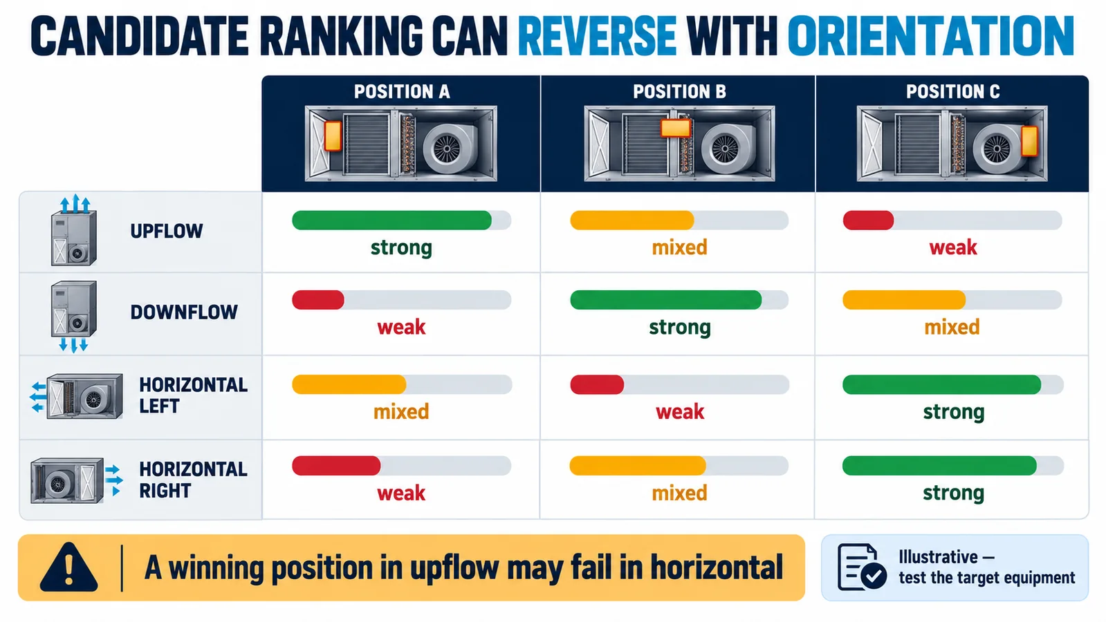
Engineers often compare several candidate positions with controlled releases. A useful scorecard considers alarm margin, repeatability, worst-case response, water exposure, obstruction risk, service access, harness complexity and manufacturing tolerance. The highest-ranked position can change with orientation.
Do not average an excellent upflow result with a poor horizontal result. Every approved configuration needs to meet its requirement. If one common location cannot do so, use orientation-specific brackets, sensing points or a different architecture and control the change in production and field instructions.
R32 and R454B need equipment-specific evidence
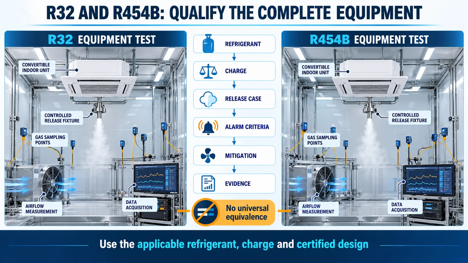
R32 and R454B are used in A2L HVAC applications, but that shared classification does not make their equipment tests interchangeable. Refrigerant composition, charge, circuit layout, release case, concentration criterion, detector calibration and mitigation design must match the applicable program.
The same mechanical location may be a useful starting candidate across closely related equipment, yet qualification should retain separate traceability to the refrigerant, sensor variant, controller configuration and certified design. Do not transfer a threshold, delay or response result without controlled evidence.
Build an orientation test matrix
For each approved orientation, cross credible release sources with fan states, environmental conditions and relevant pan conditions. Record reference concentration, detector signal, alarm transition, mitigation command, feedback and recovery. Include detector faults and communication loss if the device is part of a refrigerant detection system.
Repeat the limiting cases across manufacturing and environmental corners. Keep raw time histories, photos, unit configuration, sensor serial or lot, calibration state, software revision and pass criteria. The matrix becomes the basis for release and later change assessment.
| Test dimension | Minimum configuration record |
|---|---|
| Equipment | model, cabinet, coil, pan, insulation and accessories |
| Orientation | upflow, downflow, horizontal-left or horizontal-right |
| Release | refrigerant, charge, source, direction and test method |
| Air state | blower command, measured or confirmed state, filters and dampers |
| الاستشعار | exact variant, location, bracket, inlet direction and interface |
| Result | reference trace, sensor trace, alarm, mitigation, fault and recovery |
Control changes from drawing to field service
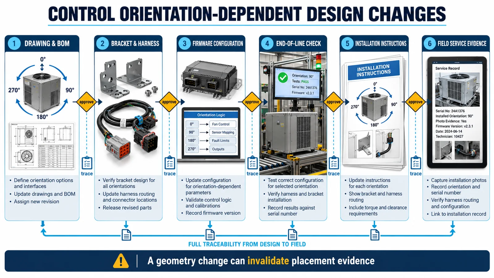
Orientation-dependent placement touches the drawing, bill of material, bracket, harness, firmware configuration, end-of-line inspection, installation manual and service record. Give each item a revision and trace it to the validation evidence. An informal bracket move can invalidate the path that was tested.
When a coil, pan, blower, insulation part, harness or sensor housing changes, perform an impact review. Use focused retesting only when the technical basis is documented. Update service instructions so a replacement sensor returns to the qualified position and inlet orientation.
Select a module for the intended refrigerant and interface
وينسن وحدة الكشف عن غاز التبريد ZRT512J is listed in the official product export as an NDIR module for R32, R454B and R290, with PWM, RS485 and UART listed as outputs. Use the current controlled variant datasheet to confirm electrical limits, protocol, dimensions, response behavior, environmental performance and qualification evidence before selection. Product data alone does not establish an approved equipment location.

Continue with the practical guides on R32 air-handler orientation locationsو ducted-air-handler placementو drain-pan and blower tradeoffs و RDS design for R32 and R454B equipment.
What to send for an orientation review
Provide the refrigerant and charge, equipment type, cabinet and refrigerant-circuit drawings, approved orientations, leak-source analysis, fan and damper states, drain design, proposed sensor zones, controller interface, alarm target, environment, annual volume and certification market. Winsen can review candidate module interfaces and the equipment-level validation plan.
Contact Winsen for an orientation-dependent sensor review.
مراجع
- حلول UL: فحص أنظمة الكشف عن غازات التبريد في معدات التدفئة والتهوية وتكييف الهواء (HVAC).
- حلول UL: المتطلبات المحدثة لأنظمة الكشف عن غازات التبريد
- حلول UL: استجابة المستشعر في أنظمة التدفئة والتهوية وتكييف الهواء (HVAC).
- مبادرة أبحاث المبردات القابلة للاشتعال AHRI
- AHRTI 9009: كشف تسرب غازات التبريد A2L في معدات التدفئة والتهوية وتكييف الهواء (HVACR).
- حلول AHRTI وUL: التقرير الفني لاستجابة أجهزة الاستشعار
