

The factory installed vs field installed RDS decision determines where the equipment assembly is completed and who verifies that it matches the approved configuration. The sensor is one part of that assembly. The bracket, harness, controller, software configuration and equipment outputs also matter. A detector can arrive mounted and connected, travel in an approved kit, or arrive installed in a position that a technician must change for a documented unit orientation. Each path produces a different handover record.
UL Solutions explains that an integral refrigerant detection system (RDS) can be factory-installed or field-installed under UL 60335-2-40. Where the equipment requires an integral RDS, it is evaluated as part of the equipment certification. The manufacturer instructions establish applicability, specified equipment and installation details. Even a factory-mounted sensor may require a position check or relocation at the job site when the manufacturer specifies it for the final orientation. UL Solutions guidance on inspecting refrigerant detection systems
Establish exactly what arrives at the job site
Use the order acknowledgement and the applicable installation instructions to identify the physical state the installer should receive. Factory-installed usually means an assembly station attaches and wires the specified parts. Factory-provisioned may describe a cabinet with prepared mounting points or an internal harness, with completion assigned to the installer. Field-installed can describe an OEM-specified kit fitted as part of the equipment installation. Ask for the controlled parts and work instructions behind those descriptions because they carry different meanings across product families.
Some installations split responsibilities across more than two stages. A factory may mount a sensor and test the controller connection, a distributor may supply an orientation-specific kit and the installer may complete the final configuration. A controls contractor may then connect a documented external interface. Record each handoff and the expected state of the equipment at that point. A packing list can show that the kit shipped. The field record must establish which kit was fitted to the individual unit and whether it reached the intended final position.
Identify the equipment configuration before picking a pathway
Collect the model, serial or date code, refrigerant, intended orientation and applicable controls revision. Match those identifiers to the equipment instructions and listing information. Ask whether the unit requires the RDS, where it belongs, and which installation path the documentation authorizes. For a split system, also capture the specified indoor and outdoor equipment combination and any controller included in the approved arrangement.
Separate the physical location of the work from the suitability of the configuration. Factory installation can reduce on-site assembly steps when the approved end state is known at the time of manufacture. An OEM-specified field kit can let the installer use the prescribed position once final orientation is known. A factory installation followed by an authorized field move combines factory assembly evidence with field evidence for the final geometry. The decision is driven by the specific equipment and instructions, with project logistics shaping the choice where more than one documented path is available. UL Solutions RDS inspection guidance
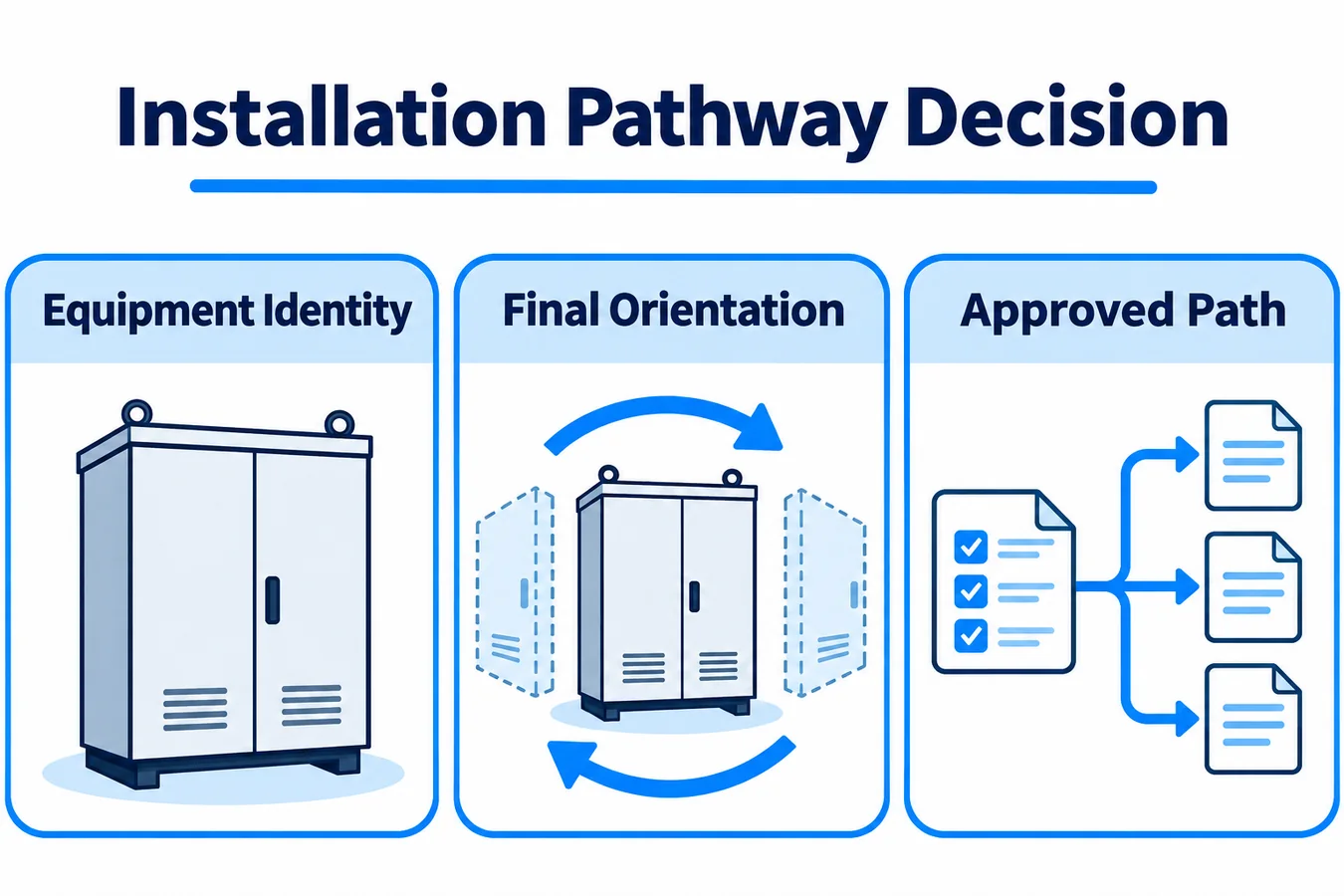
Use a pathway matrix to decide what evidence is due
Use this matrix during submittal and preinstallation review. The paths are illustrative. Actual applicability and tests come from the equipment documentation.
| Delivery condition | Evidence supplied with equipment | Field evidence to close | Decision if evidence is missing |
|---|---|---|---|
| Sensor mounted at factory in final position | Unit identity, approved configuration and factory assembly record or traceable equivalent | Confirm actual orientation, sensor position, external interfaces and any OEM-prescribed field verification | Resolve the discrepancy against the applicable instructions and obtain OEM disposition where needed |
| Sensor mounted at factory and moved under the equipment instructions | Shipment position, authorized final positions and required relocation hardware | Show the final location, orientation, harness routing and post-move checks | Confirm which instruction applies to the unit before closing the move |
| OEM-specified kit installed in field | Kit applicability, revision and controlled installation instructions | Record actual kit and unit, mounting, wiring and prescribed commissioning results | Verify kit applicability or obtain the correct documented kit |
| Replacement in an operating unit | Serial applicability, approved supersession and service instructions | Record old and new identifiers, restored configuration and prescribed return-to-service verification | Resolve part applicability and check the effect on the documented system |
An external monitor or building automation point belongs in its own row if the project includes one. Document the purpose of the point and whether it reports an event or is credited in the equipment’s mitigation sequence. That distinction determines the evidence to collect and who must provide it.
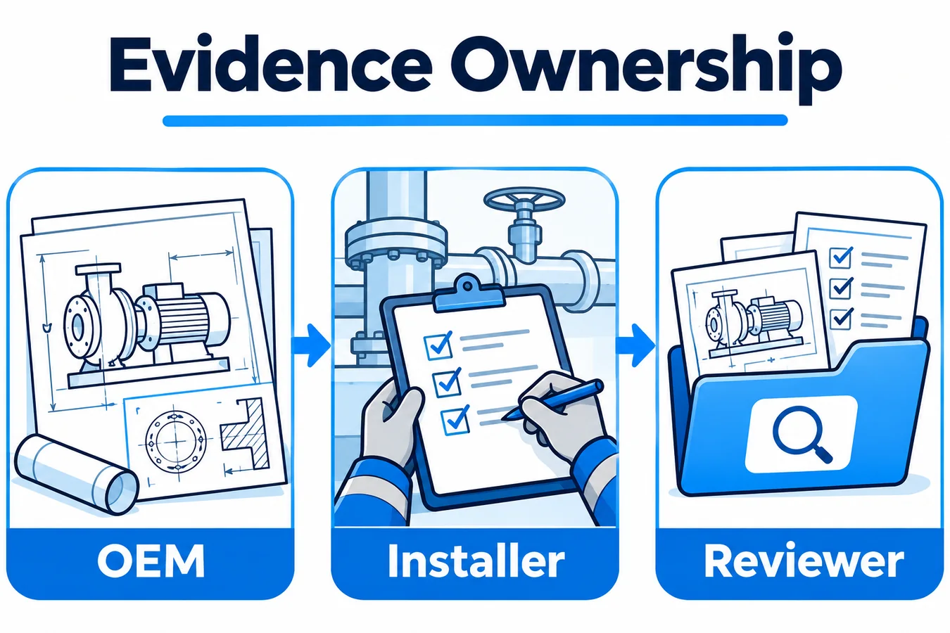
Assign responsibility for evidence before installation
The equipment manufacturer controls the supported equipment configuration, part applicability, required instructions and prescribed check methods. Manufacturing or kit fulfillment can supply the shipment record. The installer documents the configuration as assembled at the site. Commissioning or service staff record the execution and result of the applicable tests. The project reviewer closes exceptions using the project acceptance process and the relevant equipment documentation.
Assign one owner to each record and require an identifier that the next owner can look up. For example, purchasing provides the unit and kit identifiers, the installation lead records the matched parts and orientation, and the commissioning lead links a test result to the same unit. A controls contractor who provides trend data should include the equipment serial or another cross-reference alongside the controls point name. Otherwise, a trend captured from a neighboring unit can appear to close a check on the wrong asset.
Ownership becomes especially important when a unit ships late or a kit is distributed separately. The project can move an exception through procurement, installation and commissioning without losing the reason it was opened if the same record follows the unit. Give the exception an owner and an approved disposition reference. Where multiple trades use separate systems, agree on the common identifier and the location of the authoritative record.
Keep the factory traceability useful in the field
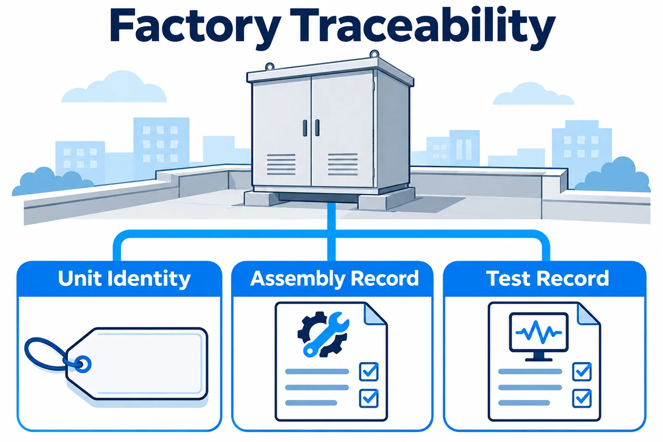
The production record should resolve the installed assembly at the level needed for service. For example, a serial number can map to an assembly part and revision, the bracket and harness versions, the controller configuration, and a manufacturing test result. Where records distinguish only by model name, a revision that changes the connector pin assignment or mounting can become hard to identify after shipment. Preserve the effective serial boundary in the parts lookup and service bulletin.
Describe what the factory test verified. A read of the module identifier can help verify communications and configuration. An end-of-line sequence can verify specified controller behavior and installed outputs within the factory setup. The factory record should make those boundaries clear so a project reviewer knows which checks remain after the unit is installed, especially where equipment orientation or external devices are decided later. When the factory sends a summary instead of raw results, make the summary traceable to the underlying test record.
Use a practical way for the field team to recover the evidence. A record available only by searching an internal lot number is difficult to use during a service call. Put a service-readable identifier on the appliance or assembly where the approved design allows it, then confirm that the parts desk can resolve an actual serial number through the live lookup. Include approved supersessions and any instruction revision that changes the work expected of the technician.
Design the field handover around the final configuration
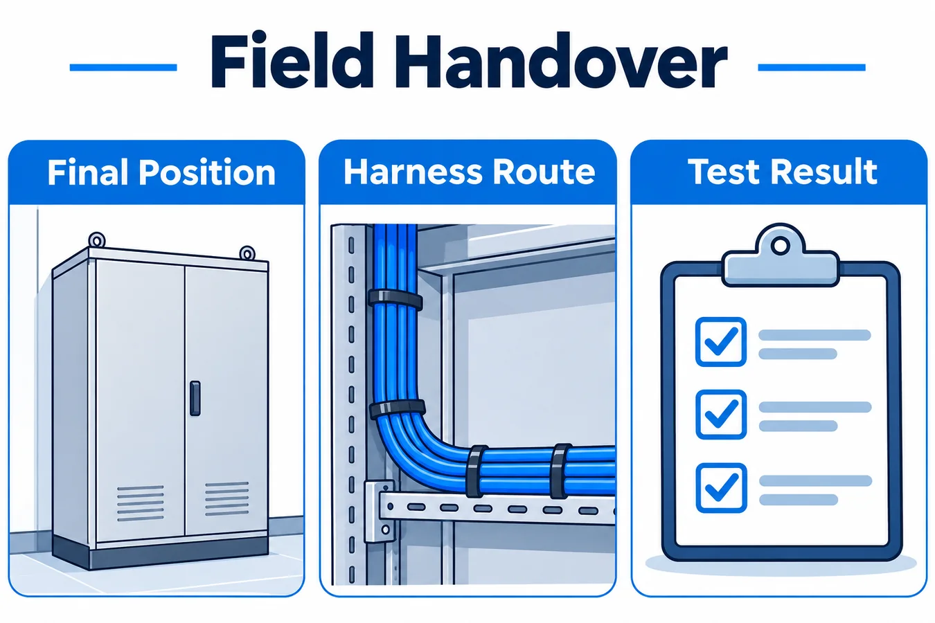
Give the installer the exact kit instructions and equipment instructions together. The field record should identify the unit and kit, final orientation, sensor position and connector destination. Where documentation permits multiple positions, identify the installed position by the drawing reference. A close photograph is useful when the inlet or latch is visible. A wider photograph or drawing reference gives the next person cabinet context and establishes which mounting point was used.
Record the harness route relative to access panels and the specified clips or protection. If the kit includes multiple bracket options or harness branches, note which ones the installer used and identify the intended status of unused parts under the instructions. If an external interface forms part of the documented response, identify its terminal, destination and owner. Record observed device behavior when the approved procedure calls for an end-to-end test.
Finish the handover by matching the equipment as received, the work as performed and the configuration accepted. A unit can be factory-tested in the same week that the OEM issues new instructions for a later serial range. The version in the field binder should match the serial under review. If an electronic form fills the document number automatically, give the installer a way to flag a mismatch instead of allowing the form to certify that the latest revision fits every unit on the project.
Distinguish test methods by what they exercise
The project test record should identify the method and the start point of the stimulus. A manufacturer-provided test mode may exercise an internal controller branch. A simulated detector input may exercise wiring or controls from a specified point. A complete test prescribed for a particular unit may include observing physical actions by the equipment and devices identified in the instructions. Where the method relies on a direct observation or proving signal, make that clear in the report.
Describe the test in steps that can be reconstructed. Capture the procedure identifier, conditions applicable to the test, tested input or channel, expected response, actual response, diagnostic indication and restoration result. When a test is repeated after correction, retain the original result and document the adjustment along with the new result. That history is particularly useful if the same fault appears across more units using the same kit or instruction revision.
Where controls are shared across trades, distinguish event visibility from action. A building management graphic can confirm that a point changed. Another observation may be required to establish that a device reached the specified state. Conversely, a device can respond as intended while a supervisory point is mapped to the wrong label. Give those outcomes separate fields so that each failure goes to the trade responsible for correcting it. UL Solutions guidance on sensor wiring and external connections
Control replacements and other post-installation changes
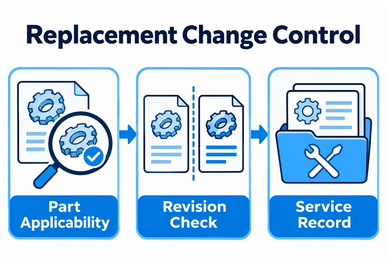
Treat a replacement as a documented change to an individual unit, including replacements that use the same service part. Check the serial applicability, installed position, bracket, harness, controller revision and any instructions that accompany the approved supersession. Similar housings may use different pin assignments, configured gases or diagnostic behavior. Resolve the part through the OEM’s supported lookup and retain the identifiers on the service ticket.
Capture the as-found condition before the repair. Photograph the installed position when useful, record controller event history and the reason for replacement, and note recent related service. After the repair, document the installed identity, revision, applicable verification and final status. This creates a record that can distinguish a recurring unit integration fault from a damaged connector or a module that was fitted to the wrong model.
An OEM change review should link the proposed substitute to its approved equipment range, update production and service documentation, and identify evidence affected by the change. If a kit is superseded in the warehouse, make the current applicability visible to fulfillment staff and retain a reference for older stock already in the field. Keep kit and unit serial histories connected so a supplier issue can be traced without sending a crew to inspect every similar cabinet on the site.
Compare the work on two hypothetical units
Assume Unit A arrives with a sensor fitted at the factory and supports a horizontal orientation under a documented relocation instruction. Assume Unit B ships with a separately boxed OEM kit specified for a particular vertical configuration. Both feed a project monitoring system. The example assumes their respective instructions define different acceptance procedures and that the monitoring points are used for reporting.
For Unit A, the factory record closes the shipment configuration. The field installer adds evidence of the horizontal mounting location, final harness routing and completion of the prescribed verification after relocation. The project commissioning record identifies the actual orientation. That record matters because a factory photograph may show the original position correctly while a field photograph shows a different position that is also correct under the applicable instruction.
For Unit B, the receiving record ties the kit to the equipment serial before the installer opens the package. The field file records kit identity, installed bracket, sensor position, connections and observed results from the prescribed procedure. The controls contractor can reference both unit serials when checking the monitoring points, even though the sensor installation histories differ.
Now assume one submittal lists the right unit family but omits its revision suffix. The record is insufficient to resolve kit applicability. The owner asks the OEM or authorized documentation channel to identify the correct revision using the installed equipment identity. The disposition is attached to that unit and reflected in the parts lookup used for future service. This resolves an actual mismatch in evidence without treating every unit in the building as the same configuration.
Assemble an acceptance checklist that can be audited
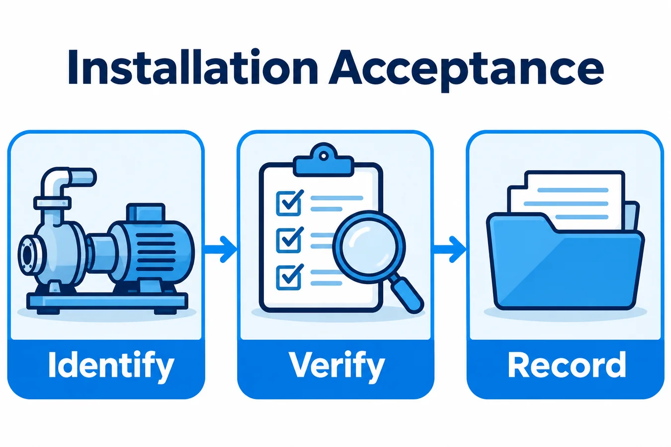
Store the checklist by unit and give each item a result, an evidence reference and an owner. A completed field can point to a drawing, a timestamped photo, a commissioning report or an OEM disposition. Include an option to mark an item outside the applicable scope with a reference, so that skipped work can be distinguished from a missed check.
- Identify the equipment model and serial, configured refrigerant, actual orientation and applicable instruction revision.
- Identify the approved installation pathway and the actual sensor assembly or kit, plus its relationship to the equipment parts record.
- Confirm the prescribed location, orientation, mounting hardware, electrical connection and harness protection using the applicable instructions.
- Record each required verification with its method, expected outcome, observed outcome and restoration result.
- Identify the external interface owner and provide the relevant result if the equipment instructions or project documents call for one.
- Resolve discrepancies with a documented disposition and record any work performed after the original test.
- Publish the accepted configuration and service instructions where the asset owner can retrieve them.
Before closeout, select one unit and follow its evidence from the asset tag back to the kit or production record, through the commissioning result and into the service lookup. Gaps discovered in that walkthrough can be corrected across the rest of the project while the installers still have access to the records.
Evaluate the total installation and service cost
Compare the pathways using the work allocated to each party and the likely cost of resolving a mismatch. A factory path may make repeatable assembly and test easier on a high-volume platform. A documented kit can accommodate a final orientation selected late on a project, with more work allocated to the installer. A factory installation that requires occasional relocation has characteristics of both. Include training, spare parts, documentation, travel to close exceptions and the cost of identifying an approved replacement after the unit is in service.
Ask purchasing to trace a sample order from quote to service. Give them an example model and orientation and have them produce the applicable equipment instructions, kit or installed assembly identifier, evidence expected on delivery and replacement lookup. If a required record is available only through an engineering contact, make its availability part of the purchase and closeout workflow. This reveals the actual administrative burden behind each equipment option.
Build a receiving check around common discrepancies
Receiving staff can find several problems before a cabinet is placed or a boxed kit is distributed. Compare the shipping labels with the submittal and look for enough information to resolve the equipment and kit relationship. For a factory-mounted assembly, the receiving record can establish what the order called for and whether the external identification is legible. For a separate kit, the same record should establish which equipment it was assigned to and whether the documented kit version was supplied.
Define a process for matching kits when many units arrive together. A project receiving ten similar units might include several successive serial ranges and two bracket revisions. A kit staged on top of a cabinet can be moved during delivery. Tie the kit to an asset identifier in the receiving log, then verify the match again at installation. When the supplier provides only a box identifier at receipt, leave space to add the assembly identifier after the package is opened.
Put time-sensitive decisions where staff can see them. A shipment discrepancy that affects which bracket or wiring diagram applies should remain open through installation scheduling. Give the issue owner access to the equipment identity, a description of the discrepancy, and the record that would close it. If the same discrepancy recurs in other deliveries, add a common supplier case while keeping the disposition tied to each affected unit.
Use exceptions to improve the handover template. For example, assume an installer discovers that a factory-mounted module is in its shipping position after a cabinet is already configured horizontally. The record can identify the instruction governing the move, the final bracket location, and the verification completed afterward. At closeout, that record is useful even when the team cannot recover the original factory photo. For the next delivery, a receiving note that flags orientation-dependent work gives the installation lead time to schedule it with the other configuration steps.
Check that the accepted asset record remains readable to a technician after the project files are archived. Use a sample serial to locate the applicable manual, installation evidence and service part. If a file contains a generic cabinet photo or lists the kit without the equipment identifier, capture the missing detail while the commissioning team can still inspect the installed unit.
Candidate module for OEM evaluation
Winsen lists the ZRT512C-A as a refrigerant detection module. For an OEM design review, request the exact configured assembly, refrigerant designation, controlled drawings, interface definition, firmware identifier and supplier change process. Evaluate the candidate against the specific factory build or field kit configuration being developed. Its applicability in an integral RDS depends on the exact equipment configuration approved and released by the OEM. Winsen ZRT512C-A product profile

Frequently asked questions
Does factory-installed mean ready in every orientation?
Check the manufacturer instructions for the final orientation. Some factory installations require a site check or relocation. If the procedure calls for a move, record the resulting position and any checks prescribed for the altered configuration. UL Solutions RDS inspection guidance
Can an installer use a field kit offered for a similar model?
Verify applicability using the exact equipment identifiers and the current controlled instructions for that serial range. Where an order includes several sizes or revisions, compare the kit against each relevant group. Use the OEM disposition to resolve a case that the published documentation leaves open.
What does an alarm shown at the building controller prove?
It can establish that a specified signal reached a supervisory point under the conditions recorded. Compare that result with the required appliance and external device behavior in the prescribed procedure. Keep the point check and the equipment result identifiable so the acceptance record can show both.
Is replacing a factory-installed sensor equivalent to fitting a new kit?
Both paths need an approved part and a record of the work. A replacement starts with an existing configuration and should document what changed and how that configuration was restored. A new kit installation starts with the shipping configuration and establishes the complete installed assembly for the first time.
Who signs the acceptance record?
Use the responsibilities established by the project and the applicable procedures. A practical record identifies the person who performed each check, the reviewer who accepted the result and the source of any disposition resolving an exception. Associate those records with the same asset identifier.
Request an OEM installation and service package
Provide the equipment family, target refrigerant, installation orientations, intended delivery pathway and controller interface. Ask the OEM and module supplier to identify the exact proposed assemblies, the drawings and instructions that govern their use, the evidence required at factory and field handover, and the supported replacement process. Start with one representative serial range and walk the configuration from factory order to commissioning and service. Resolve any gaps in documentation before rolling the pathway out across the rest of the model family.
Review the ZRT512C-A product listing in submit the equipment details for an OEM integration review.
