
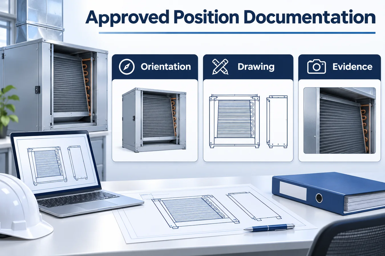
Refrigerant sensor approved positions belong in the controlled definition of an appliance. A location that works in one cabinet orientation may have a different relationship to gravity, condensate, gas transport and service access when the equipment is converted. The documentation needs to tell engineering, production and service exactly which construction the evidence covers and how to recognize it.
This guide assumes an illustrative indoor equipment family offered in several orientations. It describes a method for recording positions after the engineering program has established the applicable requirements and validation approach. The released OEM instructions and certification documentation determine the actual approved construction. UL Solutions explains that an integral detection system is evaluated within the equipment and installed according to manufacturer instructions. UL Solutions integral RDS guidance
Define the approval object precisely
Begin with the whole configuration represented by a position record. Include the equipment model and revision, orientation, coil and pan construction, detector configuration, bracket, harness and controls. If the approved location depends on an accessory or conversion kit, include that kit in the configuration identifier. The position is a feature of this combination.
A record labelled “horizontal” can conceal more than one assembly. Horizontal left and horizontal right can change where the connection compartment, active drain pan and service panel sit relative to the installed gravity direction. A smaller cabinet can use a different bracket while retaining the same exterior family name. Use distinct rows wherever a difference can affect transport, environment or installation.
State who has authority to approve each record and which evidence is required. Mechanical engineering can own the drawing, controls engineering the interface and a designated review owner the release disposition. A supplier drawing helps define a component but cannot by itself approve its location within the appliance. Make that division clear in the document workflow.
Keep proposed and released positions visibly distinguishable. Prototype photographs, trial brackets and exploratory test notes can otherwise circulate into assembly work as though they describe the production configuration. Use revision and status information that survives export into a service PDF or a printed work instruction.
Establish orientation and datum conventions
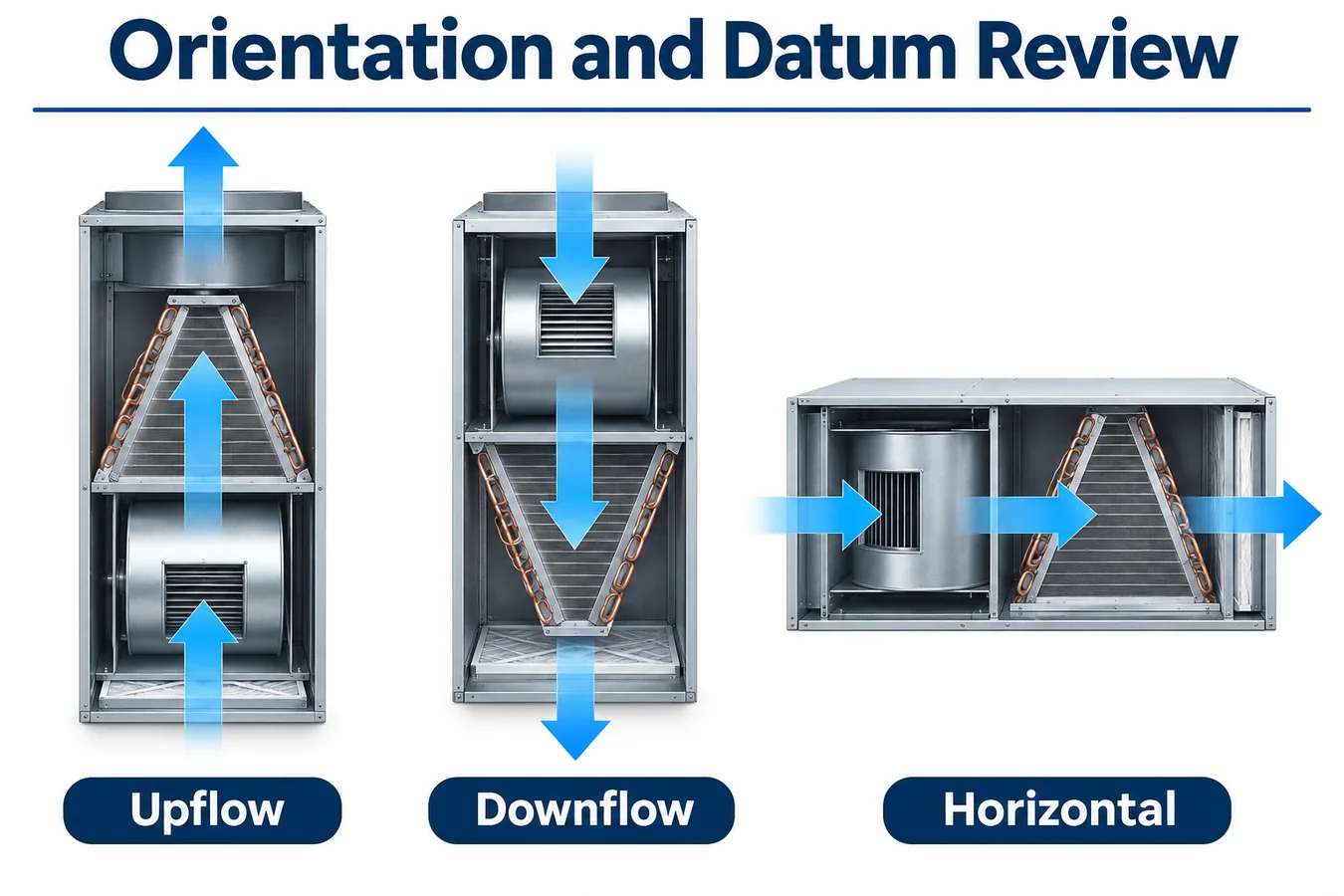
Define the coordinate system before adding dimensions. Specify the viewing direction, installed gravity direction, normal airflow and cabinet datums. Use fixed physical features that remain identifiable after conversion. Avoid relying on the page edge or a photograph’s apparent “left” when the technician can approach the cabinet from another side.
An orientation sheet should show how the coordinate system relates to the equipment nomenclature. If “right hand” refers to the connection side when facing the access panel, say so and illustrate that view. Use the same definition in bracket drawings, harness instructions and the variant matrix. A consistent datum makes an inspection repeatable across teams.
Control the inlet and connector orientation independently where the component documentation makes them relevant. A bracket can occupy the intended cabinet region while the detector is rotated incorrectly within it. Record the locating features, allowed rotation and assembly constraints in a way that can be checked on the installed unit.
Manufacturer manuals demonstrate how orientation-specific instructions can differ. Carrier’s 45VMV instructions identify sensor relocation for particular equipment orientations. Use that as an example of the documentation task, then derive the actual positions from the model being developed and its evidence. Carrier indoor equipment installation instructions
Build a configuration identifier that survives service
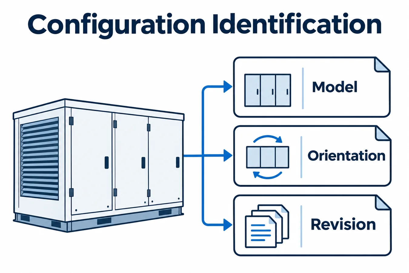
Tie each record to model identifiers and the serial or revision range that uses the construction. Add option and conversion codes when they change the position. A service reader should be able to start from the installed equipment identity and select one applicable drawing without interpreting the engineering history.
Use a stable position identifier in the configuration ledger and link it to the current drawing revision. If the drawing changes without changing the underlying position, preserve the relationship and document the change scope. If a new pan or bracket creates a different construction, evaluate whether a new identifier makes the distinction clearer.
Consider legacy units explicitly. A later bracket may supersede an earlier part for some models while requiring another harness or installation detail. Record the permitted replacement combination and the evidence supporting it. Service information must distinguish a direct replacement from a kit that changes the assembly.
Check identifiers across systems. The bill of materials, production instruction, test report and service parts list should resolve to the same construction. A mismatch between an engineering shorthand and an orderable part can make a technically correct location impossible to restore in the field.
Write the position record as an engineering contract
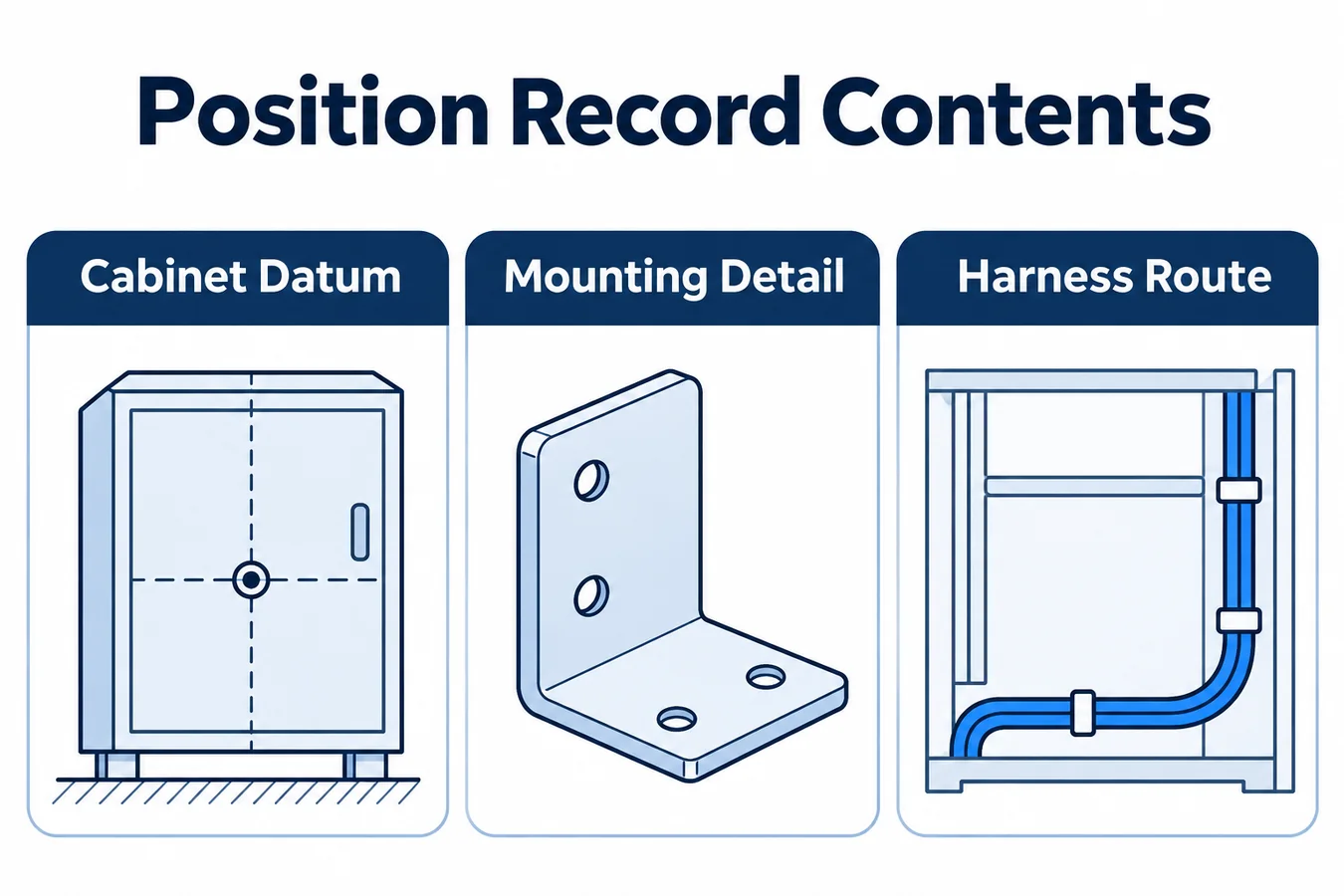
A complete record describes what is installed, where it is located, how it is oriented, which parts locate it and what evidence supports it. Include the bracket and fastener details at the level needed to reproduce the validated construction. Reference controlled drawings for dimensions and tolerances rather than transcribing uncontrolled values into several documents.
Show the sensing inlet’s relationship to nearby pan edges, insulation, covers and air passages. A nominal center point can be inadequate when a cover or foam feature changes the accessible inlet volume. Include the relevant geometry in a section or detail view. The record should distinguish locating features from surrounding features shown only for context.
Describe the harness route and connector retention that allow the assembly to remain in position during panel closure and service. Include the allowed service loop and attachment features where these affect inlet access or exposure. Identify any component-specific mounting limits by reference to the exact supplied configuration’s documentation.
Connect the record to test and review evidence. Use identifiers that locate the source cases, operating conditions and applicable variant comparisons. The approval signature or release status should reflect that evidence review, with open exceptions recorded where the organization’s process permits them.
Document the transport rationale behind each position
Record which release regions the position is intended to cover. Identify the refrigerant-bearing sources, the expected path into the sensing region and the operating states that change that path. Keep the rationale concise enough for a change reviewer to use, while linking to the detailed test protocol and results.
A location may receive gas through one route when the fan is idle and another route during operation. A pan lip, partition or insulation seam can make the relationship orientation dependent. The record should name the geometry involved so a later change to that feature triggers the correct review.
Separate the inlet’s exposure from the detector’s response after exposure. In the evidence record, identify how the lab observed each part of the chain. If a response is delayed, a reviewer needs to know whether gas reached the inlet late or whether the component and controller consumed the interval.
Avoid reducing the rationale to a generic statement about gas behavior. The actual cabinet, installed orientation and airflow establish the transport problem. The position record captures what the equipment team demonstrated for that construction and which conditions bound the claim.
Include environmental and mechanical constraints
Evaluate the installed environment for every position row. Relevant differences can include condensate exposure, local temperature, vibration, panel movement and access during cleaning or replacement. Compare these conditions with the controlled component documentation for the exact detector configuration.
Record features added to manage exposure, such as a cover, shield or routing detail, as part of the construction. Those features can affect both environmental exposure and gas access. A change intended to protect the detector may require renewed transport work if it alters the inlet’s exchange path.
Review tolerance and assembly variability. A bracket that shifts within a slot can place the inlet on opposite sides of a local divider. Foam placement or an adhesive bead may vary across production. Identify which characteristics need controlled limits and how inspection will establish them.
For an illustrative ceiling unit, assume a position lies close to a removable drain assembly. Document the relative features and perform a service mock-up. The evidence must establish that ordinary removal and restoration of the drain assembly preserve the intended inlet access, orientation and harness retention.
Make installation illustrations unambiguous
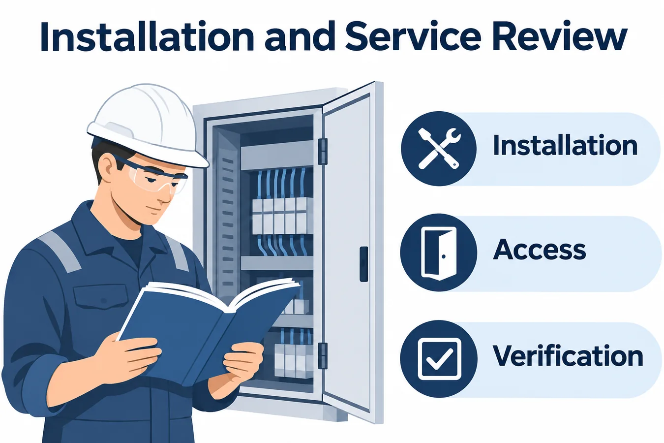
Use one principal view for each configuration and add detail views where hidden features matter. Keep the orientation label and equipment identifier beside the image. Show enough surrounding structure to let a reader locate the feature without guessing which panel has been removed.
Use callouts with a clear destination. A leader line should terminate on the bracket, connector or locating feature being described. If two components overlap in the view, use a section or an exploded detail. A photograph with a broad circle around several parts can leave the important relationship ambiguous.
Distinguish required assembly features from explanatory arrows. Airflow arrows, gravity arrows and part installation motion have different meanings. Use a legend and consistent graphic conventions. Avoid placing a decorative arrow where a reader might interpret it as a relocation instruction.
Validate the illustration with someone who did not create the drawing. Give that person the equipment identity and the relevant service task, then observe whether they select the correct sheet and locate the feature. Record confusion about viewpoint, orientation or hidden geometry and correct the document before release.
Build an orientation and evidence matrix
The example below uses fictional configurations. It shows the relationship between a position record, construction differences and the evidence that would support a release decision.
| Configurare | Position record scope | Difference to assess | Evidence entry |
|---|---|---|---|
| Vertical baseline | Standard coil, pan and bracket | Initial release path and environment | Baseline transport, response and access results |
| Reversed vertical option | Alternate active drain and assembly details | Gravity relationship and moisture route | Dedicated orientation trials and inspection features |
| Horizontal left option | Approved conversion kit | Partition geometry and harness access | Converted assembly trial and service restoration |
| Horizontal right option | Different kit arrangement | Mirror assumptions and local inlet exposure | Separate comparison against the actual construction |
| Later service kit | Replacement bracket and harness | Legacy fit and assembly restoration | Compatibility and affected validation evidence |
Add the drawing, component, firmware and instruction revisions to the controlled version. Identify the owner and status for each evidence entry. An unresolved row should state the remaining question in terms that a test or document review can close.
Use the matrix to expose assumptions about symmetry. Two drawings can look like mirrored versions while the pan, coil connection area or access openings remain asymmetric. Review the actual parts and operating envelope before allowing a test result to carry across.
Link change control to the evidence mechanism
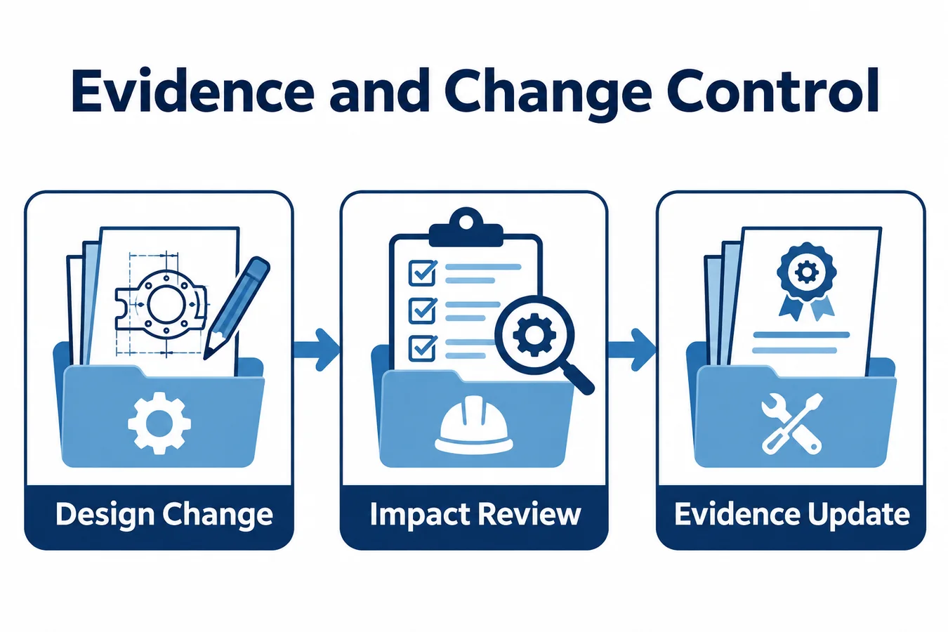
Define change triggers using the rationale behind the position. A new pan may affect the gas path and wet exposure. A different connector can affect service access and electrical continuity. A controller revision can affect input eligibility or mitigation timing while leaving the mechanical location unchanged.
For each change, identify affected position records and the portion of evidence that may be inherited. Explain the basis for inheritance and the additional work needed. A mechanical drawing review may close one question while a system trial remains necessary for another. Keep those dispositions separate.
Preserve earlier releases and their applicability. If a drawing is superseded, service still needs to identify what was installed on legacy units and what replacement arrangement is permitted. Use revision history to explain the construction change, not merely that a picture was updated.
Make the approval owner review the evidence boundary. A change can expand the marketed model family, permitted orientation or field kit list without changing the nominal position. Confirm that the resulting coverage claim still matches the tested configurations and the current release documentation.
Walk through a conversion kit decision
Assume a vertical unit has a released position record tied to a factory bracket. A proposed horizontal conversion kit uses a revised pan and relocates the detector through a kit-specific bracket. The detector electronics remain the same. The change request needs a new configuration row and a clear relationship to the existing component evidence.
First, compare the mechanical construction and source map. The new pan creates a different low volume near a coil connection. The lab selects cases that challenge gas movement from that region with the fan idle and operating. The position record links the kit bracket to the actual converted cabinet and the source cases.
Next, review the service sequence. The installer must identify the orientation, select the kit parts and route the harness while converting the unit. A mock-up checks whether the instructions distinguish the new bracket from the factory arrangement and whether the restored panel interferes with the inlet or harness.
Finally, compare controller and detector interfaces. Existing component evidence may apply when the exact supplied configuration and electrical environment remain equivalent. If the harness length or route changes, identify the resulting electrical work. Release the row when the transport, environment, assembly and interface questions have each been resolved.
Verify production and service against the same record
Build production checks around observable characteristics. Confirm the exact part, bracket orientation, retention features and relevant surrounding geometry. Use a controlled sample or fixture where visual judgment would be inconsistent. Record the configuration identifier with the unit’s manufacturing history.
Provide service with the applicable drawing and replacement compatibility information. A technician should be able to verify the equipment identity, compare the installed construction and restore the intended assembly. If a replacement kit introduces different parts, include the necessary instructions and the permitted legacy combinations.
Distinguish a service function test from the qualification evidence. A defined function test can establish portions of the electrical and physical response chain. The transport evidence remains associated with the released construction. Service checks help confirm that construction was restored, while the lab work establishes what it covers.
Review recurring field observations against the position ledger. Reports that identify model, orientation, serial range, kit and part revision can lead to a repeatable engineering case. Use those observations to improve instructions or identify a construction question that needs renewed review.
Assemble a release package that can be audited
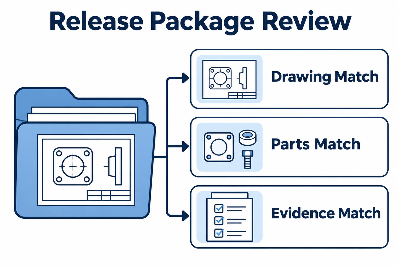
The package should let a reviewer start at a model and orientation and follow the chain to parts, drawing, evidence and installation instructions. Include the source map, position record, relevant test protocol and acceptance disposition. Keep approved exceptions and unresolved work visible in the same review system.
Check document exports. A drawing can lose a revision field, a note can become unreadable in a service PDF or a hyperlink can disappear from a printed instruction. Ensure that essential identifiers and orientation information remain available in the formats used by production and service.
Review images for fidelity to the released construction. An editorial illustration may explain orientation categories, while an installation drawing must show the actual features needed to assemble the unit. Label the purpose of each visual and use controlled technical illustrations for location instructions.
Perform a final trace exercise on one baseline and one converted configuration. Ask a reviewer to identify the installed parts, applicable position and evidence without relying on undocumented team knowledge. Resolve any missing connection before the package becomes the reference for shipment or service.
Evaluate the detector candidate within the position record

Winsen lists R454B and R32 among the target refrigerants for the ZRT512C-A family. The exact orderable configuration can be evaluated as a candidate for an equipment program. Request its controlled drawing, mounting constraints, gas configuration, interface behavior, environmental evidence and revision identification before attaching it to an approved position record. Winsen ZRT512C-A product information
Use representative samples to confirm that the actual bracket, connector and harness allow the intended construction. The candidate’s family name should resolve to the exact part used in qualification and procurement. Keep the supplier evidence and equipment validation linked through those identifiers. ZRT512C-A product candidate
Work through a horizontal conversion drawing change
Imagine that a cabinet originally released in two upright orientations gains a horizontal conversion kit. The sheet-metal cabinet is unchanged, but the kit adds a different drain pan, two clips and a relocated access cover. A designer proposes adding a third view to the existing approved position drawing because the original bracket bolts to the same row of holes. The drawing reviewer should begin by identifying which geometric relationships are carried forward and which are changed by the conversion.
In the new view, show the direction of gravity and airflow, the conversion pan and the interface to the access cover. Identify which hole or formed feature establishes the sensor’s location and which defines bracket orientation. A row of similar slots needs a dimension or uniquely identifiable datum. Indicate any identifying features that will be visible during assembly or service, especially if the label faces a panel after the sensor is installed. Keep the drawing readable at the size used in the actual instruction set.
Review the harness independently. A clip originally above the pan may be beside it after rotation. A small service loop may contact the panel when it is closed. Identify the route and retention features on the correct orientation drawing, and run a service trial with the unit at its representative installed angle. Verify that a technician can identify and restore the approved position through the stated access. Retain photographs showing the final assembled condition and the reference features that made the location recognizable.
Next compare the physical exposure assumptions with the evidence for the previous orientations. The changed pan may alter how a release passes beneath the coil, and the access cover may change the boundary of a pocket. Identify which source and operating combinations are affected. Give the validation owner a controlled drawing and conversion kit identifier so the relevant test records can be attached to the right matrix row. If the drawing revision introduces only an annotation on an older view, record the reason that existing evidence still applies to that view.
Confirm that a different reader can rebuild the configuration
Choose a finished unit or representative build and give a reviewer its model, option code and serial information. Ask the reviewer to identify the applicable installation view, the detector part and revision, the bracket and harness items, and the supporting evidence reference. Then ask them to verify the installed position using the actual access route. Record any ambiguity they encounter, such as a feature named differently in the drawing and manual or a conversion kit with an insufficiently specific identifier.
Apply the same exercise to a service replacement. Check that the parts lookup identifies the approved configuration and any associated hardware. Review whether a technician can distinguish right-hand and left-hand arrangements without inferring from a generic picture. If a label, drawing note or photo is needed for that decision, make it part of the controlled record. Cross-check the new version against the assembly instructions and approved parts information before release.
A configuration record is complete when the drawings, service material and validation record identify the same construction. Keep an example of the final lookup with the release evidence so a later change review can repeat the exercise and identify where the document set diverges.
Întrebări frecvente
Is a photograph enough to define an approved position?
A photograph can help a reader recognize the construction. The record also needs configuration identity, datums, locating features, orientation constraints and evidence links. Use drawings or details for relationships that perspective or hidden geometry makes ambiguous.
Can mirrored equipment share one position record?
It can share evidence where the equivalence case supports the actual construction. Compare coil connections, pan details, partitions, airflow and service access. Keep distinct records when the installed geometry or parts differ, even if some evidence is inherited.
Who approves a field relocation?
The equipment program defines that authority through its controlled release and service process. A proposed relocation needs a configuration record, impact review and applicable evidence. The exact manufacturer instructions establish the approved field construction for the released equipment.
What should a service replacement record include?
Include equipment applicability, exact replacement configuration, required bracket and harness parts, installation detail and restoration checks. Identify any supersession limits for legacy units and connect the service kit to the evidence supporting its use.
Request an OEM documentation review
Prepare the model and orientation matrix, cabinet sections, proposed datum conventions, detector and bracket identifiers, harness routes and evidence references. Include an example service conversion or replacement sequence so the review can address how the validated assembly will be restored.
Ask the sensor team for the exact candidate documentation and sample configuration needed to complete the position records. Use the discussion to resolve mounting, environment, interface and revision questions that affect the release package. Share the equipment context through the local application contact. Contact the refrigerant sensor team
