

Three locations often look attractive during an R32 detector design review: a low point near the drain pan, a position near the blower inlet, and a position in the return-air path. Each can be effective in the right cabinet. Each can also fail for a predictable reason.
The drain-pan region may see a concentrated downward plume but also water. The blower inlet may collect air from several leak paths but changes dramatically between fan states. Return air may offer broad sampling and service access while diluting a small release. The final choice must come from one consistent equipment test matrix.
Compare locations against the same five criteria
Use the same measures for every candidate:
- time from release to a valid detector response;
- minimum concentration and duration seen in the slowest credible case;
- resistance to condensate, overflow, cleaning fluid and contamination;
- robustness across fan, filter, panel and orientation states;
- repeatable installation and service access.
Do not let one strong result, such as a high concentration in a blower-off test, hide a failure in another state.
Near the drain pan: strong plume interception, high water risk
R32’s higher molecular weight gives a concentrated cloud a downward buoyancy tendency. Cabinet surfaces and the coil can also guide a release toward the pan. A sensor near this route may respond quickly with the fan off.
The same area receives normal condensate and is exposed to blocked-drain overflow, installation tilt, pan slosh and maintenance spray. Water can block an inlet, contaminate the sensing path, corrode a connector or create an electrical fault. Position the inlet in the air path adjacent to the pan, outside the normal and foreseeable water envelope. Any shield must preserve gas access.

Near the blower inlet: shared airflow, changing concentration
The blower inlet can sample air drawn from a large portion of the coil compartment. With the fan running, this may provide coverage for several release sources. It can also expose the detector to high velocity, vibration and a diluted plume.
When the blower is off, the inlet is no longer a collection point created by forced flow. A local plume may settle elsewhere and never reach it quickly. Test fan off, normal speeds and the specified mitigation speed. Evaluate recirculation near the scroll and whether the sensor body disturbs the inlet or adds noise.

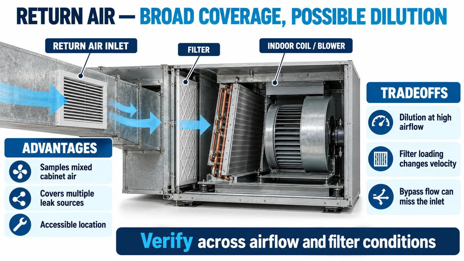
In return air: broad coverage, possible dilution and bypass
A return-air position can sample mixed air and can be accessible for service. In a ducted unit it may represent air from several coil regions. In a wall-mounted mini-split, the return inlet and filter can similarly provide a repeatable upstream location.
High airflow can reduce the local concentration from a small release. Filter loading changes velocity distribution. Gaps around the filter or a cabinet bypass can carry refrigerant around the sensing inlet. A return-air position is therefore credible only after tests at the relevant airflow range and filter conditions.
Blower state can reverse the ranking
With the blower off, natural convection, leak momentum and enclosure geometry dominate. A low candidate may receive the highest early concentration. With the blower on, forced transport may make a blower or return-air candidate respond first while diluting the low pocket.
This is why a placement study should not report a single “best” point without its operating state. Plot concentration and installed-sensor output for every candidate on the same time axis. The qualifying candidate must meet the response requirement across the full state set, not win one test.
Production geometry creates pockets and short circuits
Pan lips, coil frames, baffles, insulation edges, cable bundles and the blower scroll create low-velocity pockets and bypass streams. These features can retain refrigerant, block it from the inlet or guide it away from a candidate.
Use the production-intent cabinet, harness routing and insulation. A clean CAD volume or an open-panel prototype can overstate mixing and service access. Record any change to these flow-defining parts as a potential placement-validation impact.

Build a candidate comparison matrix
Create one row for each credible release and operating condition and one group of columns for each candidate. Record response time, peak and time-integrated concentration, alarm output, water exposure, fault behavior and accessibility.
| Candidate | Potential strength | Main risk | Required evidence |
|---|---|---|---|
| Near drain pan | early access to a low plume | condensate and overflow | dry-zone proof plus blocked-drain test |
| Near blower inlet | coverage of forced-flow paths | fan-off miss or high dilution | fan-off and full airflow range |
| In return air | mixed-air coverage and service access | filter, bypass and dilution effects | clean/loaded filter and bypass tests |
The illustrative scores in the accompanying graphic are not product data. Populate the real matrix from the target equipment.

Test credible releases, not only convenient injection points
Select sources from the refrigerant circuit: flare or field connection, distributor, header, return bends, braze joints and service tubing. Represent release direction and nearby impingement surfaces. A convenient injection tube in the center of the cabinet may create a plume that no real failure produces.
Include small or shielded releases that could be slow to reach a detector, subject to the equipment qualification basis. Document release rate or quantity, temperature, pressure state, fan command, panels, filters and environmental conditions so candidates can be compared fairly.
Protect reliability while preserving gas access
Keep the inlet clear of sheet metal, filters, insulation and wiring. Avoid direct high-speed impingement when it can introduce contamination or unrepresentative dilution. Route the harness away from moving parts, hot tubing and power electronics, and prevent water from wicking along it.
Check vibration, connector retention, cleaning exposure and service handling. If a splash shield is needed, validate response with the shield installed and at manufacturing tolerance limits.
Validate response, fault behavior, mitigation and recovery
An equipment-level test should record the reference concentration at candidates, detector output, alarm or fault state, controller decision, actuator command and recovery. Challenge sensor disconnection, communication timeout and other supported diagnostics separately from gas exposure.
Define recovery criteria in the control specification. Avoid an automatic reset based only on elapsed time unless that behavior is part of the evaluated design. Freeze the bracket, inlet orientation and harness only after the slowest response and fault cases pass with appropriate margin.

Use research results as inputs, not universal coordinates
Published experiments on wall-mounted R32 air conditioners show that operating condition, leak position and supply airflow affect dispersion. A 2024 study reported faster response for detectors inside the tested indoor unit than for a room detector and identified a preferred internal area for that specific geometry. AHRI research has also evaluated mitigation effectiveness across equipment types.
These findings support internal, equipment-specific testing. They do not eliminate it. A different coil, pan, control-box position, blower or cover can change the concentration field.
Match the component to the control and validation strategy
Se ZP201 refrigerant gas detection module is listed in the official product export as a semiconductor R32 module with TTL-level output. Winsen also lists NDIR R32 options including ZRT510 ja MH-Z1542B-R32. Confirm the exact variant, output behavior, power, dimensions, environmental limits, lifetime and current qualification evidence from the controlled datasheet.

Read the related guides on mini-split R32 sensor integration- R32 sensor placement in ducted air handlers ja NDIR versus MOS refrigerant sensing.
What to send for a placement review
Provide the refrigerant and charge, coil and cabinet drawings, drain and overflow paths, blower curve and states, filter range, credible release list, controller interface, alarm target, environmental limits, annual volume and certification market. Winsen can review the sensing architecture and the test matrix needed to choose among drain-pan, blower and return-air candidates.
Contact Winsen for an R32 placement review.
Viitteet
- UL Solutions: Inspecting Refrigerant Detection Systems in HVAC Equipment
- AHRI Flammable Refrigerants Research Initiative
- Applied Energy: Experimental Study on R32 Leakage from Wall-Mounted Air Conditioners
- Journal of Refrigeration: Influence of R32 Leak Detection Position on Indoor Safety
- NIST Chemistry WebBook: Difluoromethane (R32)
- UL Solutions: Sensor Response in HVAC Systems
