
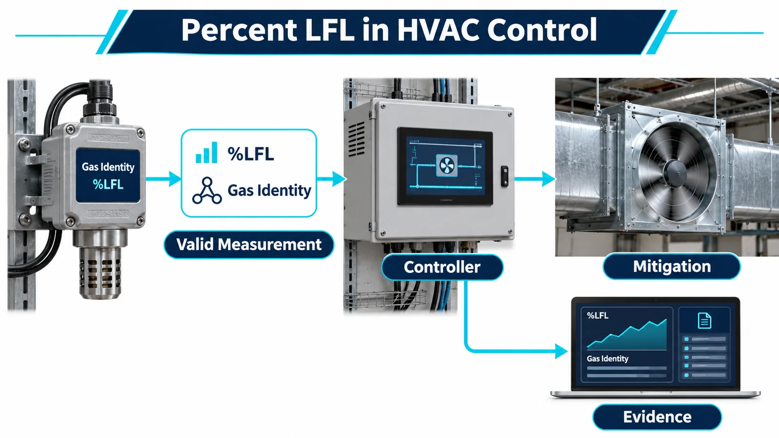
Percent LFL is attractive because it expresses concentration relative to a refrigerant’s lower flammability limit. That does not make it a universal, context-free number. The value depends on refrigerant identity, property basis, sensor calibration, concentration units and conversion ownership. The equipment alarm threshold also belongs to a controlled safety design with tolerances, response timing and mitigation evidence.
A robust percent LFL refrigerant sensor threshold implementation therefore begins with data semantics, not a number copied into firmware. The controller must know which refrigerant is measured, what the reported quantity means, whether it is valid, which released configuration owns the threshold and what action/feedback follows a decision.
This article intentionally does not prescribe a universal alarm threshold. Current applicable equipment requirements, controlled refrigerant data, certification decisions and the released equipment safety design govern the value and response for a specific product.
1. Define LFL and Percent LFL Carefully
The lower flammability limit is a refrigerant-specific concentration boundary defined under specified test/reference conditions. Percent LFL expresses a measured concentration as a fraction of the chosen LFL basis. In conceptual form:
percent LFL = measured refrigerant concentration / controlled LFL concentration × 100
The simple equation hides critical inputs. Both concentrations must use compatible units and reference conditions. The refrigerant identity and property source must be controlled. For blends, use the correct released refrigerant definition. Do not infer a value from a similar refrigerant.
Percent LFL is not percent by volume. A reading of “10” could mean 10 ppm, 10% volume or 10% LFL depending on the interface. Every data item needs gas and unit context.
The property basis can be revised or differ across documents. Assign one approved source in the project and record its revision. Avoid hard-coded constants copied independently into test spreadsheets, detector firmware and controller code.
2. Percent LFL Is Gas-Specific
R32 and R454B do not share one interchangeable percent-LFL scale. The same volume concentration can represent different fractions of each refrigerant’s LFL. The sensor’s optical response and calibration are also gas-specific.
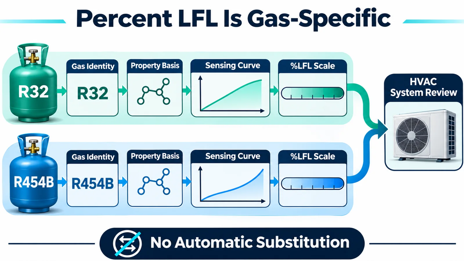
The controller should identify the refrigerant through part configuration, electronic identity or a protected equipment parameter. It should reject a sensor/configuration mismatch rather than accept plausible numbers. A wrong-gas detector may report zero in clean air and respond to a leak, making the error difficult to notice.
If one product family supports several refrigerants, maintain separate calibration and threshold configuration records. Shared housings and communication protocols do not establish equivalent response.
Service replacement needs the same discipline. The replacement part, controller gas setting, property basis and released threshold must remain aligned. Record the combination with the equipment serial.
3. Decide Where Conversion Happens
The detector may report percent LFL directly, volume fraction, ppm or an alarm state. Choose one released interface and define conversion ownership.
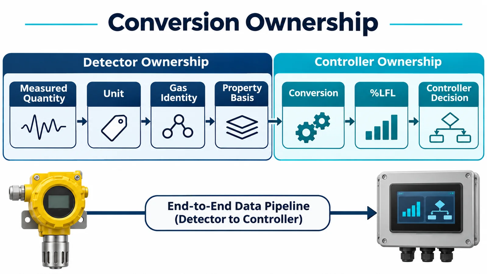
If the detector reports percent LFL, confirm the refrigerant calibration and LFL basis. The controller should not convert it again. If the detector reports volume concentration, the controller conversion needs a controlled gas-specific property and clear reference conditions. If a discrete alarm is used, understand its preset semantics and tolerance.
Avoid conversion in multiple layers. A detector converts to ppm, a gateway converts to percent volume and a controller converts to percent LFL; each rounding, scaling or gas selection creates an error opportunity. Prefer an end-to-end data contract with test vectors.
Document quantity, unit, scaling, resolution, invalid codes, gas identity and revision. Verify the actual bytes or voltage through the complete controller path, including displays and logs.
4. Assign Threshold Ownership
The released threshold should have one authoritative owner. It may reside in a factory-preset detector or in equipment controller configuration, depending on the certified architecture. A supervisory display value is not automatically the safety decision.
Record the requirement or safety analysis behind the threshold, applicable tolerance, firmware/configuration identifier, approval and verification evidence. Protect it from casual field adjustment. If service tools can change it, use authorization, range controls, logs and compatibility checks.
Do not place slightly different copies in detector, indoor controller, outdoor controller and cloud. If redundancy is intentional, define synchronization and disagreement behavior. Otherwise, one layer can alarm while another continues normal operation.
Threshold ownership also includes reset/recovery values, persistence, hysteresis and latching. These are part of the decision, not UI details.
5. Build a System Tolerance Stack
A nominal threshold does not describe when a real equipment system responds. Include sensor calibration uncertainty, manufacturing tolerance, environmental compensation, drift, gas transport, sampling, communication, controller quantization, filtering, persistence and actuator time.
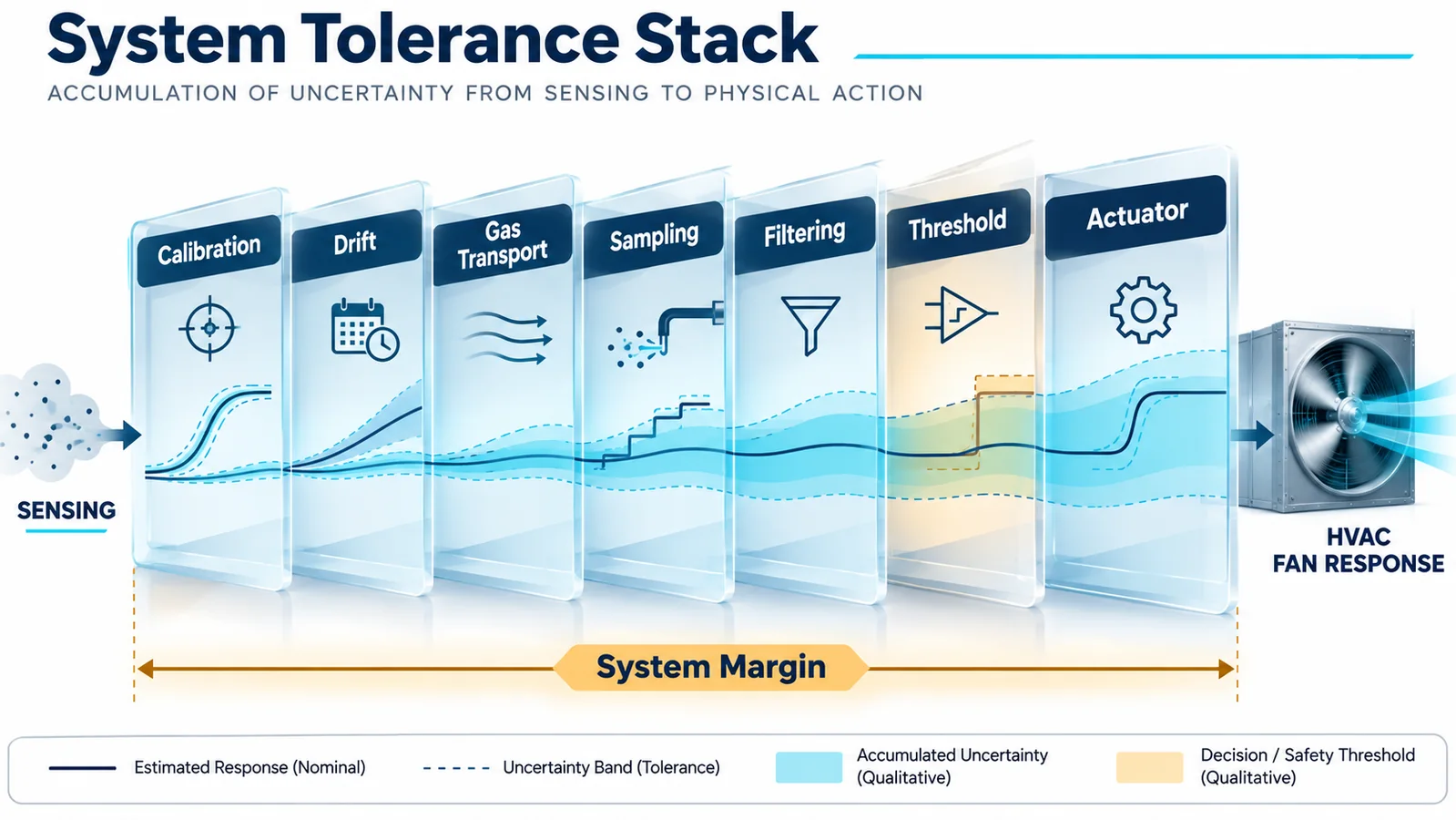
Separate concentration uncertainty from timing. A sensor can be accurate but exposed late because of cabinet transport. A detector can alarm promptly while the controller samples slowly. An actuator can receive a command but move late.
Use controlled error budgets and worst-case/appropriate statistical methods consistent with the applicable safety evaluation. Avoid double-counting margins, but do not omit supplier tolerance because nominal samples performed well.
Evaluate drift and aging at the system threshold. The applicable requirements and controlled supplier evidence determine life tests. Verify the installed response after relevant environmental conditioning.
The goal is not to publish the stack as a marketing number. It is to select and validate a released configuration that achieves required system response with margin.
6. Design Sampling and Filtering Deliberately
Refrigerant signals can contain noise, transients and airflow-driven fluctuations. Filtering may reduce nuisance transitions but also delay a rising leak. Sampling and filter design belong in the response budget.
Use representative step, ramp and pulsed profiles. Test slow rises and rapid releases, not only a stable calibration point. Evaluate communication jitter and missing samples. Define what happens when data become invalid during filter history.
Avoid averaging invalid or stale values. Reset or preserve filter state according to a controlled rule after power cycle, fault and service. A filter initialized to zero can create a temporary bias; a filter initialized from old memory can preserve stale conditions.
If both detector and controller filter the signal, characterize the combined delay. Do not tune each layer independently. Keep coefficients version-controlled and linked to system tests.
7. Use Hysteresis, Persistence and Latching With Purpose
Hysteresis separates entry and exit decisions, reducing chatter as concentration fluctuates near a boundary. Persistence requires a condition for a defined time or sample count. Latching holds the safety state until controlled reset.
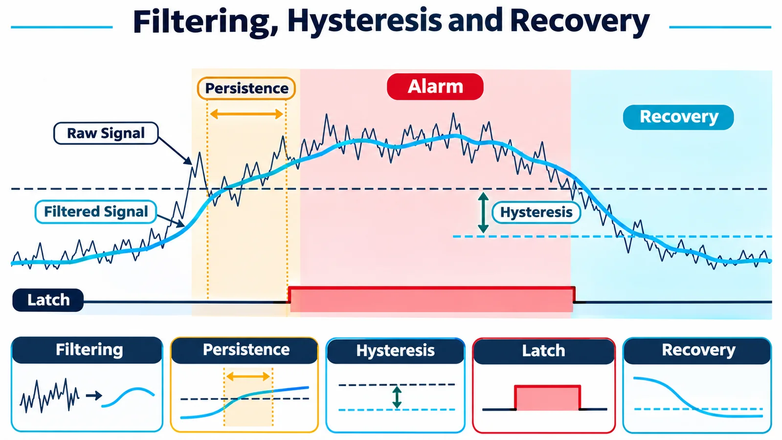
Each mechanism trades nuisance resistance against delay or recovery. Derive settings from requirements and system validation rather than habit. Test rising, falling and oscillating profiles with fan changes.
Recovery should not be based only on one below-threshold sample. Require valid data and any released ventilation/actuator conditions. If a detector fault occurs during an alarm, preserve the appropriate protective state and distinguish the diagnostic condition.
Document whether reset is automatic, local manual or service-controlled. Protect reset paths from thermostats or remote systems that do not know whether the physical hazard has cleared.
8. Represent Validity and Faults Alongside the Value
A concentration without quality information is incomplete. The controller data model should include refrigerant identity, value, unit, valid state, alarm state if supplied, diagnostic fault, communication status, timestamp/sequence and configuration version.
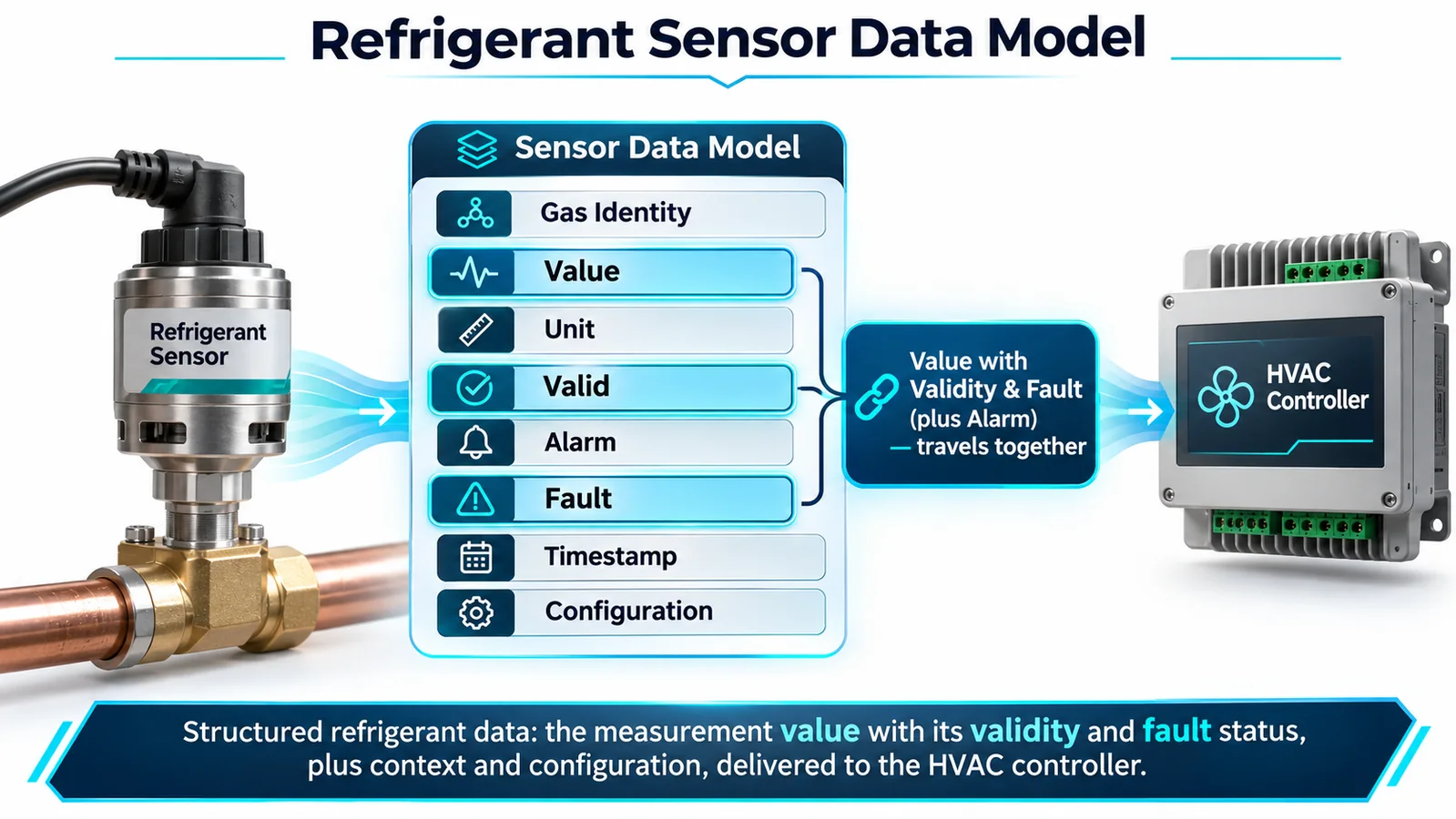
Warm-up, zeroing, calibration mode and self-test should be invalid or separately identified, not reported as normal clean air. Communication timeout and frozen data should create explicit faults. Analog interfaces need open/short/out-of-range diagnostics.
The controller should never substitute zero for missing data. Define a safe response to invalid information using the released equipment design. Alarm and fault may command similar mitigation while remaining distinct in logs and service messages.
Carry units into engineering logs and test tools. A raw register displayed without scale or gas code is a common source of commissioning error.
9. Separate Sensor Alarm From Equipment Action
A detector alarm is an input to the equipment state machine. The controller decides actions according to the released safety architecture and applicable requirements. Those actions may include compressor control, fan/blower state, heat/ignition-source management, valves, dampers, annunciation and communication.
Define priority over comfort, defrost, demand response and service commands. Test simultaneous events and race conditions. A normal task should not re-enable equipment after the safety task acts.
Verify critical actions with physical feedback. A stop command does not prove a compressor stopped. A fan command does not prove airflow. Identify stuck relays, failed motors and contradictory feedback as mitigation faults.
System evidence should synchronize detector signal, controller decision, commands and physical state. Measuring only the sensor response misses downstream latency and failure.
10. Understand Preset and Adjustable Architectures
Some detector systems provide a factory-preset output; others provide concentration for controller decision. The applicable equipment requirements and certification design may restrict adjustment. Confirm current controlled requirements rather than assuming that a configurable module can be field tuned.
For a preset architecture, verify gas, preset semantics, tolerance, startup, fault and output timing from controlled documents. The controller should supervise signal integrity and execute the released response.
For a controller-owned threshold, protect configuration, include error/timing budgets and verify the complete chain. The sensor’s measurement range alone does not justify the chosen threshold.
Do not add a hidden “service threshold” that bypasses the released decision. Test modes should stimulate the state machine without changing safety parameters unless a controlled procedure explicitly requires it.
11. Validate Gas Transport With the Threshold
The detector sees local concentration, not total leaked mass or room average. Cabinet airflow, barriers, release momentum and location determine the signal. A threshold that works in a calibration chamber may be reached later—or not at all—at the installed inlet.
Use credible release points and all relevant fan/off/transient states. Measure detector output and, where needed, local concentration to explain transport. Test production-intent panels, seals, filters, brackets and accessories.
If one location has strong exposure but water risk and another is dry but weakly exposed, resolve the mechanical design rather than compensating with an unsupported threshold change. Thresholds cannot repair missing gas access robustly.
Repeat limiting cases and evaluate manufacturing tolerance. Preserve the location and gas path in production and service controls.
12. Integrate the ZRT510 Family Conservatively
Winsen lists ZRT510 refrigerant-specific NDIR module variants for R454B and R32, with controller-oriented communication options in current product information. The shared product image does not mean calibrations are interchangeable. Exact model code, gas, range, output, protocol, preset behavior, response, diagnostics, environmental limits and qualification evidence require current controlled project documents.

Request the complete ordered variant, calibration and LFL basis, quantity/unit, protocol scaling, validity and fault definitions, startup timing, filtering/preset semantics, mechanical/inlet restrictions, environmental limits, drift/life evidence and change notification.
Local product evidence flags certification wording as conditional; do not publish certification or compliance claims without current certificate/test evidence. Likewise, web-page numbers should not replace controlled datasheets where differences exist.
The equipment OEM owns location, controller interpretation, threshold configuration, mitigation and system evaluation. A detector module does not make the final HVAC equipment compliant.
13. Build Verification From Unit Tests to Releases
Use layered verification:
- software unit tests for scaling, units, gas selection, filtering, hysteresis, faults and configuration;
- interface tests with recorded detector frames or controlled signals;
- hardware-in-loop tests for timing, communication loss and actuator I/O;
- gas exposure of the installed detector;
- full equipment release tests with production-intent hardware and environment.
Include boundary values, invalid codes, stale data, gas mismatch, corrupted configuration, power cycle and simultaneous alarm/fault cases. Verify logs and operator messages as well as actions.
Keep golden test vectors traceable to the approved gas/unit/property basis. When sensor protocol, firmware or threshold configuration changes, rerun the affected layers.
14. Control Evidence and Release
The release record should link applicable requirement, refrigerant property basis, sensor model/calibration, threshold/preset, tolerance analysis, controller firmware/configuration, test results and approvals.
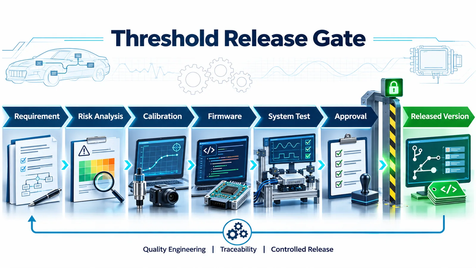
Configuration tools and manufacturing records should confirm the installed gas and threshold revision. End-of-line testing should verify identity, validity, alarm/fault handling and critical outputs. Audit functional exposure as required by the control plan.
Changes to refrigerant, sensor, calibration, LFL basis, coefficients, interface, sampling, filtering, threshold, actuator or system airflow require impact assessment. Define regression tests from the current limiting cases.
Service replacement and controller-board updates must restore the released combination. Prevent default or wrong-gas parameters from entering operation unnoticed.
15. Common Failure Modes
Watch for these recurring errors:
- Treating percent LFL as percent volume.
- Using an R32 property or calibration for R454B, or the reverse.
- Converting in both detector and controller.
- Omitting gas identity and unit from registers/logs.
- Copying a generic threshold without equipment requirements.
- Ignoring sensor tolerance, drift or environmental compensation.
- Filtering twice without analyzing combined delay.
- Replacing invalid/stale data with zero.
- Using command echo as actuator feedback.
- Allowing service tools to edit threshold without traceability.
- Qualifying an open cabinet and releasing a sealed production unit.
- Assuming a shared product image means variant interchangeability.
Each failure can produce data that look reasonable. Prevent them with explicit interfaces, configuration identity and end-to-end tests.
16. Engineering Release Checklist
Bestätigen Sie Folgendes:
- Refrigerant identity and LFL property basis are controlled.
- The sensor output quantity, unit and scale are unambiguous.
- One layer owns any conversion and one layer owns the released threshold.
- Gas-specific calibration matches the installed refrigerant.
- Sensor, environment, drift, transport, software and actuator tolerances are considered.
- Sampling/filtering delay fits the system response budget.
- Hysteresis, persistence, latching and reset are validated.
- Validity, stale data, faults and gas mismatch are explicit.
- Safety priority and physical actuator feedback are proven.
- Installed gas transport reaches the detector in limiting configurations.
- Product claims use current controlled evidence.
- Firmware/configuration and threshold evidence are traceable.
- Manufacturing and service reject unsupported combinations.
17. Ask the Right Supplier and OEM Questions
For the detector supplier: Which exact gas is calibrated? What quantity and unit are reported? Which LFL basis is used for percent-LFL output? What are validity, alarm, fault and timeout semantics? What tolerances, environmental effects, drift and change controls apply?
For the controller team: Where is conversion performed? Who owns the threshold? How are gas identity, units, invalid data, filtering and recovery represented? What prevents wrong configuration or stale data?
For the mechanical team: Which releases reach the inlet across orientations and fan states? Can water, insulation or service block it? What production controls preserve the gas path?
For compliance and validation: Which current requirements govern the threshold and system response? Which limiting cases and tolerances demonstrate the released design? What evidence must be retained?
18. Trace the Threshold From Requirement to Executable Code
A threshold should have an auditable path from the governing requirement to the controller behavior. Begin with a requirement statement that identifies refrigerant, property basis, represented quantity, unit, applicable equipment configuration, required action and source document revision. Add the allocation: whether the detector asserts an internal alarm, the equipment controller compares a transmitted value, or both. A bare number in a calibration file is not a complete requirement.
Translate that requirement into explicit software terms. Define comparison direction, equality behavior, numeric representation, scaling, rounding, update period, permitted range and treatment of missing or invalid values. State whether filtering occurs before or after unit conversion and which layer owns persistence, hysteresis and latching. If multiple controllers receive the value, document which one has authority to command mitigation and how conflicting states are resolved.
Configuration controls should make the wrong gas or unit difficult to deploy. Prefer typed parameters or enumerated calibration identities over an unlabelled floating-point value. The build process should reject unsupported combinations of detector, gas, firmware and equipment model. At startup, the controller should verify whatever identity and configuration evidence the interface provides. Where the interface cannot report identity, manufacturing and service controls must compensate with part-number, connector, label and programming safeguards.
Verification should include boundary-value tests immediately below, at and above every decision point. Add invalid, stale, out-of-range and rapidly changing inputs; power interruption; communication recovery; configuration mismatch; counter rollover if applicable; and sequences that exercise persistence and hysteresis. Test the released compiled artifact and parameter set, not only a spreadsheet model. The expected result should include both logical state and physical equipment response.
Traceability is most useful when it survives change. Link the requirement, risk control, code or configuration object, review record, unit test, hardware-in-the-loop test, equipment test and released version. When a refrigerant property source, detector calibration, filter or threshold changes, the links identify affected evidence. This prevents an apparently small parameter edit from bypassing system analysis.
19. Interpret Field Data Without Redefining the Safety Function
Field data can improve reliability, but it must not quietly rewrite the released safety behavior. Service logs may reveal nuisance transitions, stale communication, water-related faults, installation damage or unexpected operating states. Those observations should initiate controlled investigation. They do not by themselves justify raising a threshold, lengthening persistence or suppressing a fault in deployed software.
Record context alongside the value. Useful fields include equipment model and software revision, detector part and configuration identity, refrigerant, value and unit if available, validity, alarm/fault state, operating mode, commanded mitigation, feedback, timestamp quality and the transition that caused the record. Without configuration and state, a concentration-like number is easy to misinterpret. A service display should clearly distinguish raw or filtered engineering data from a certified alarm decision.
Treat field measurements as system observations rather than laboratory reference results. Gas transport, inlet condition, airflow, condensation, installation variation, sensor tolerance and logging rate all influence what is recorded. Compare recurring patterns across equivalent configurations and reproduce them in controlled tests before assigning cause. One transient near a displayed threshold may reflect sampling or rounding; repeated loss of validity during defrost may indicate an environmental or integration issue.
Change review should ask whether the proposal affects gas specificity, detection time, false-negative risk, nuisance response, mitigation timing, fault coverage or compatibility. Re-run the relevant tolerance analysis and limiting equipment tests. Update labels, service literature, manufacturing configuration and traceability records where necessary. Keep old and new versions distinguishable so that field support does not apply the wrong interpretation.
The best field loop is conservative and diagnostic: collect enough information to locate the weak link, reproduce it, correct the design under change control and verify the complete detection-to-mitigation chain. It preserves the released threshold as an engineering requirement while using real-world evidence to strengthen the system around it.
Data governance matters as much as collection. Define who can retrieve logs, how long they are retained, how serial or configuration identifiers are protected and which engineering team may authorize a parameter change. Separate service observations from controlled compliance evidence; a cloud dashboard export may support investigation, but it does not replace a calibrated test record with known stimulus, timing and equipment configuration. If field software performs unit conversion for display, retain the original transmitted quantity and metadata so analysts can reproduce the transformation and detect a wrong gas or property basis.
Trend review should focus on transitions and cohorts. Compare equivalent equipment models, detector revisions, installation orientations and software releases. Look for repeated invalid-data intervals, alarms without confirmed mitigation, configuration mismatches or recovery patterns that correlate with defrost, cleaning or power events. Predefine escalation criteria so that a low-frequency but safety-relevant pattern reaches engineering promptly. The objective is not to optimize the displayed curve; it is to verify that the released decision architecture remains valid in production and to identify when controlled requalification is required.
Abschluss
Percent LFL is a useful engineering representation only when refrigerant identity, property basis, calibration, units and conversion are controlled. The HVAC controller needs more than a number: it needs validity, fault context, configuration, a released threshold owner and a verified path to physical mitigation. There is no responsible universal threshold for every project.
For an engineering review, provide refrigerant, detector model/calibration, output quantity/unit, controller architecture, threshold requirement, sampling/filtering, intended actions/feedback, equipment geometry, annual volume and target certification market.
Referenzen
- UL Solutions – Inspektion von Kältemittelerkennungssystemen in HVAC-Geräten
- UL Solutions – Aktualisierte Anforderungen für Kältemittelerkennungssysteme
- UL Solutions – Sensorreaktion in HVAC-Systemen
- AHRI – Forschungsinitiative für brennbare Kältemittel
- AHRTI 9009 – Leckerkennung von A2L-Kältemitteln in HVACR-Geräten
- Copeland – A2L-Produktlösungen
- Winsen — ZRT510 R454B Refrigerant Sensor Module
