
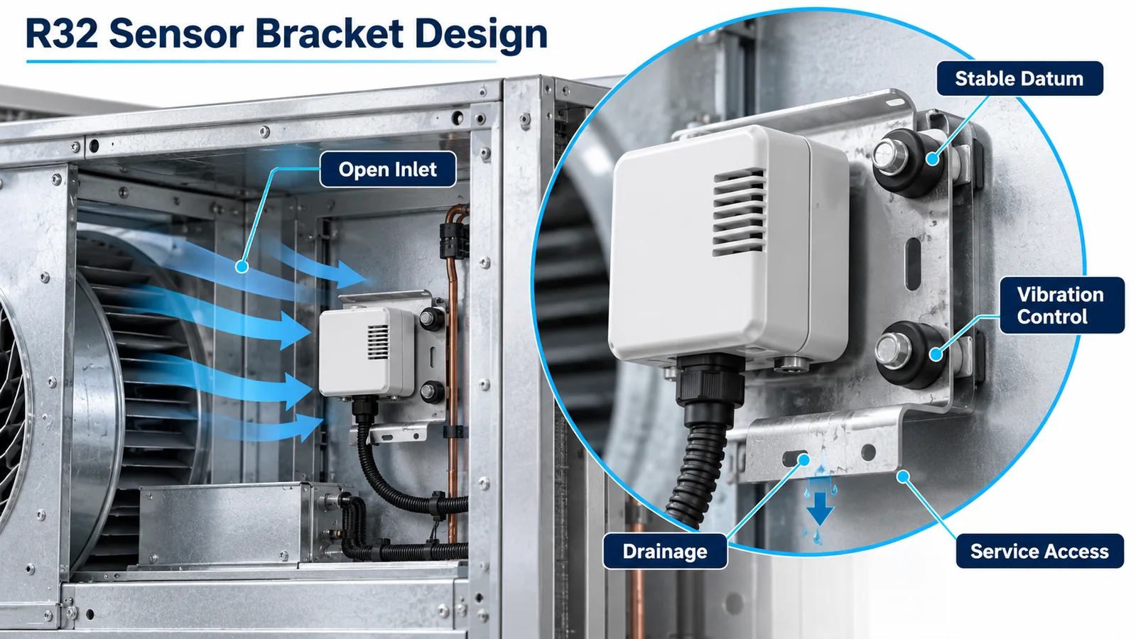
The mounting bracket for an R32 detector is easy to classify as low-risk sheet metal. In reality, it controls where the gas inlet sits, how much open air surrounds it, which vibrations reach the sensor, where condensate drains, how the connector is loaded and whether a replacement returns to the qualified position. The bracket is therefore part of the sensing function, not generic hardware.
A robust R32 sensor mounting bracket design converts a validated sensing location into a repeatable production assembly. It must preserve representative gas exposure across tolerance, vibration, water, corrosion, service and supplier variation. A bracket that looks strong in CAD can still create a stagnant pocket, resonate with compressor excitation or collect a film of water over the inlet.
This guide presents a mechanical engineering method for OEM integration. Exact clearances, materials, loads and tests must come from the detector’s controlled documents, the HVAC equipment environment, applicable requirements and the manufacturer’s qualification plan. No universal dimension or alarm value is implied.
1. Write a Functional Bracket Specification
Do not start with thickness and hole size. Start with the functions the assembly must preserve:
- hold the exact detector variant in the qualified location and orientation;
- keep the gas inlet open to the representative flow or diffusion field;
- avoid creating a gas or water pocket around the inlet;
- survive equipment vibration, shock, shipping and service cycles;
- protect the connector and maintain harness bend radius/strain relief;
- drain water away and resist the actual corrosion environment;
- fit across cabinet, detector and harness tolerances;
- allow assembly, inspection and replacement without ambiguity;
- retain performance after environmental and life conditioning.
Translate these into drawing characteristics and validation criteria. For example, “inlet unobstructed” becomes a keep-out volume measured from a detector datum. “Correct orientation” becomes an asymmetric locator. “No water accumulation” becomes defined slope, drain-edge and wet-test requirements. A functional specification makes the bracket reviewable by airflow, controls, manufacturing and service teams.
2. Establish Datums From the Qualified Gas Field
The detector position should be tied to stable equipment datums that also define the release and airflow geometry. A panel edge that shifts between options may be a poor primary datum. A coil frame, structural rail or formed chassis feature may provide better repeatability, provided it is stable over production and service.
Define detector location and inlet direction in three dimensions. Include the sensor manufacturer’s required orientation, if any, and identify which surface controls height, lateral offset and rotation. Tolerances should reflect functional coverage, not just what sheet metal can hold.
Where the HVAC product has multiple orientations, determine whether the bracket moves, rotates or changes. Do not allow a symmetric hole pattern to support an unqualified orientation. Create part or position controls that match the orientation-specific validation plan.
Document the accepted installation with section views and photographs. Mark the gas inlet, connector, keep-out volume and drainage direction. Assemblers and reviewers should not have to infer which vent in a complex housing is the active inlet.
3. Preserve Gas Inlet Clearance
Gas must reach the sensing path without being blocked, short-circuited or trapped. Nearby walls, flanges, insulation, cable bundles and shields can alter diffusion and local flow. The effect depends on the detector inlet geometry and application airflow, so use controlled supplier guidance and system tests to set clearances.
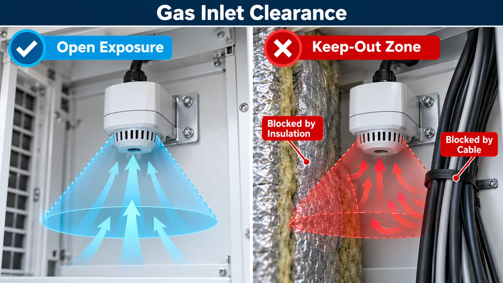
Create a three-dimensional keep-out zone around each relevant opening. Check it against nominal and worst-case surrounding parts. Include flexible items such as foam, wire and insulation, not just rigid CAD solids. Consider assembly relaxation, thermal expansion, water swelling and service displacement.
Avoid deep recessed pockets unless testing shows acceptable exchange. A protective hood should block droplets or impacts while remaining open to representative gas. Fine mesh, filters and membranes can add diffusion delay, capture dust or absorb liquid; they require validation and change control.
Use visualization and response tests with the final bracket. Smoke can reveal airflow but does not reproduce refrigerant density or phase. Tracer or controlled refrigerant release tests establish actual system response. Compare bracket variants using the same release and instrumentation to isolate mechanical effects.
4. Avoid Self-Created Stagnation and Bypass
A bracket often forms a small shelf or cup. An upward lip can trap liquid. A close parallel wall can create a dead layer. A shield open on the wrong side can receive clean air while a release passes behind it. Review the assembly as a flow component.
Use simple path questions: Where can gas enter? Where can it leave? Can debris or water close either path? Does fan flow push representative gas through the inlet or around the entire assembly? In fan-off conditions, does gravity-driven migration reach the sensor or settle in a separate low pocket?
Rounded openings and generous cross-sectional area can reduce sensitivity to minor alignment. However, mechanical protection may need localized guards. Keep guards outside the controlled inlet keep-out and validate impact protection together with gas response.
If the bracket is mounted near a panel seam, include panel leakage and pressure. A sensor that responds only because a development panel leaks may lose exposure when production adds sealant. Conversely, a production gap can direct gas through the bracket. Preserve the intended path deliberately.
5. Design Stiffness With a Vibration Model
Bracket stiffness is not simply maximum thickness. The sensor mass, cantilever length, bends, ribs, fastener spacing and boundary stiffness determine natural frequencies and motion. Compressor, blower, fan, pump and transport excitation can overlap those modes.
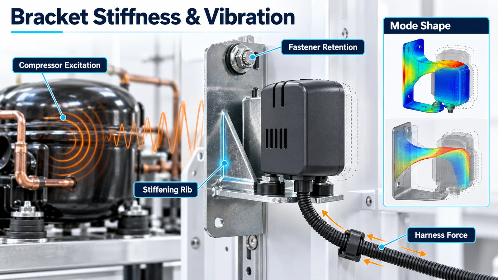
Build a simple dynamic model early. Include the sensor and connector/harness mass, realistic joint stiffness and the supporting panel. Use modal analysis to identify mode shapes and strain locations. Then measure production-intent assemblies because sheet-metal joints, clips and cable forces are difficult to model precisely.
Avoid long unsupported tabs and sharp bend transitions that concentrate stress. Add formed ribs, return flanges or shorter load paths when they improve mode separation and durability. More material is not always better: moving a resonance or stiffening the support can be more effective than thickening a flexible cantilever.
The harness can damp or excite the assembly. A tight cable applies static torque; a loose service loop can strike the cabinet. Include actual routing and temperature-conditioned cable stiffness in tests. Inspect connector fretting, fastener loosening, housing damage and changes in inlet position after vibration.
6. Control Fasteners and Joint Behavior
Select the joint around service life, not initial assembly. Screws, rivets, clinch nuts, welds, tabs and clips each change stiffness, repeatability and repairability. If the sensor is service-replaceable, repeated removal should not degrade the chassis thread or shift the datum.
Use captive or retained hardware where loose fasteners could enter a blower or electrical area. Define torque and tool access. Prevent a technician from substituting a longer screw that contacts the sensor housing or blocks a vent. If thread-locking material is used, evaluate chemical compatibility and service procedure.
Joint slip can change dynamic response even when the bracket does not visibly fail. Witness marks, torque audits or displacement measurements can reveal movement. For snap features, test insertion/extraction force after thermal and chemical aging. A clip that becomes brittle or loose can rotate the detector.
Where the supporting panel is thin, reinforce the load path rather than increasing bracket stiffness alone. A rigid bracket on a flexible wall simply moves the motion to the wall. Test the complete subassembly and final equipment.
7. Build a Functional Tolerance Stack
Tolerance analysis should cover more than hole alignment. Important outputs include inlet clearance, height relative to release/airflow features, connector engagement, service-tool access, cable bend, shield clearance and drain slope.
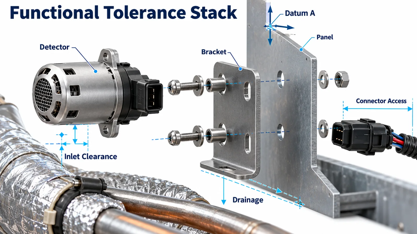
List contributors from detector housing, bracket forming, fastener clearance, support-panel position, adjacent insulation, harness length and accessory parts. Use worst-case or statistical methods consistent with risk and process capability. Flexible items need measured distributions rather than ideal CAD dimensions.
Avoid using large slotted holes without a positive locating feature. Slots can simplify assembly while allowing the detector to drift anywhere in the slot. Use a datum pin, formed stop or fixture that sets the safety-relevant position before tightening.
Verify tolerance extremes physically. Build or adjust assemblies representing the limiting gas-path and service-clearance conditions. Repeat gas exposure and water tests where geometry changes could matter. A dimensionally acceptable stack still needs functional evidence.
8. Design Drainage Before Adding a Splash Shield
The best water control begins with location, slope and gravity. Place the detector outside drip lines and below no reservoir that can overflow. Orient surfaces so water runs away from the inlet and connector. Use a drip edge to break surface flow and a cable drip loop to prevent water migration along the harness.
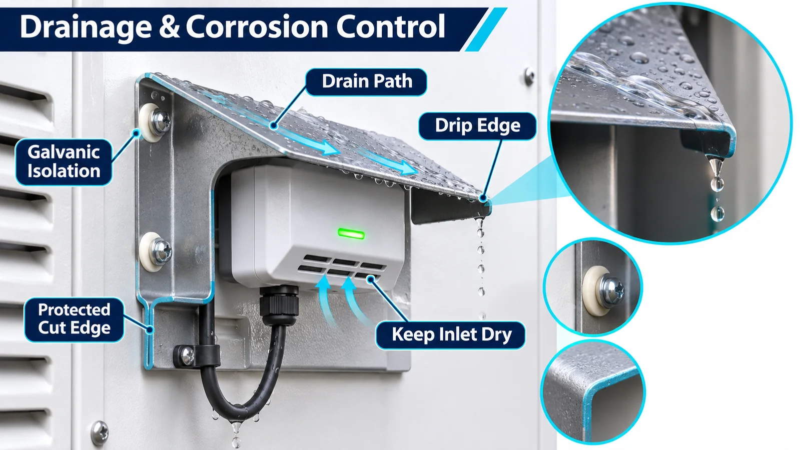
A splash shield should intercept expected droplet directions while remaining open on the gas-access sides. Give it a drain path that cannot clog easily. Avoid horizontal seams or folded hems that retain water. If condensation can form on the bracket itself, ensure it does not run into the detector.
Test more than a gentle vertical drip. Consider wind-driven rain, coil-cleaning spray, drain overflow, condensation and water carried by the cable. Observe the assembly during and after exposure. Then run diagnostics and gas-response checks to detect retained moisture or residue effects.
Freezing can turn a small retained volume into an obstruction or mechanical load. For outdoor or low-temperature applications, include freeze/thaw with the final materials and drainage geometry.
9. Select Materials as a Galvanic System
Bracket material and finish must work with the cabinet, fasteners, detector hardware, condensate chemistry and outdoor atmosphere. Dissimilar metals connected by water can corrode even when each material performs well alone. Cut edges, scratches and fastener interfaces are common initiation sites.
Map the galvanic couples and electrical contacts. Select compatible materials or use coatings and isolators that survive assembly. Ensure an isolating washer does not reduce joint stability or create an ungrounded condition that conflicts with EMC design. Coordinate mechanical, corrosion and electrical requirements.
Evaluate coating coverage after forming and fastening. Powder coat can crack at tight bends or alter grounding. Plating thickness can change hole fit. Stainless steel can still create galvanic issues with aluminum or coated steel. Use representative condensate, cleaners and salt exposure for the installation market.
After corrosion conditioning, inspect not only appearance but also joint torque, stiffness, drainage, connector condition and gas response. Rust flakes or coating delamination can block an inlet before structural failure occurs.
10. Make Assembly Poka-Yoke Visible
The bracket should only accept the sensor in the qualified orientation. Use asymmetric holes, pins, tabs or shaped interfaces. Make the connector direction natural and provide a retained harness path. Avoid mirror-image mounting positions that appear equivalent but face the inlet into a wall.
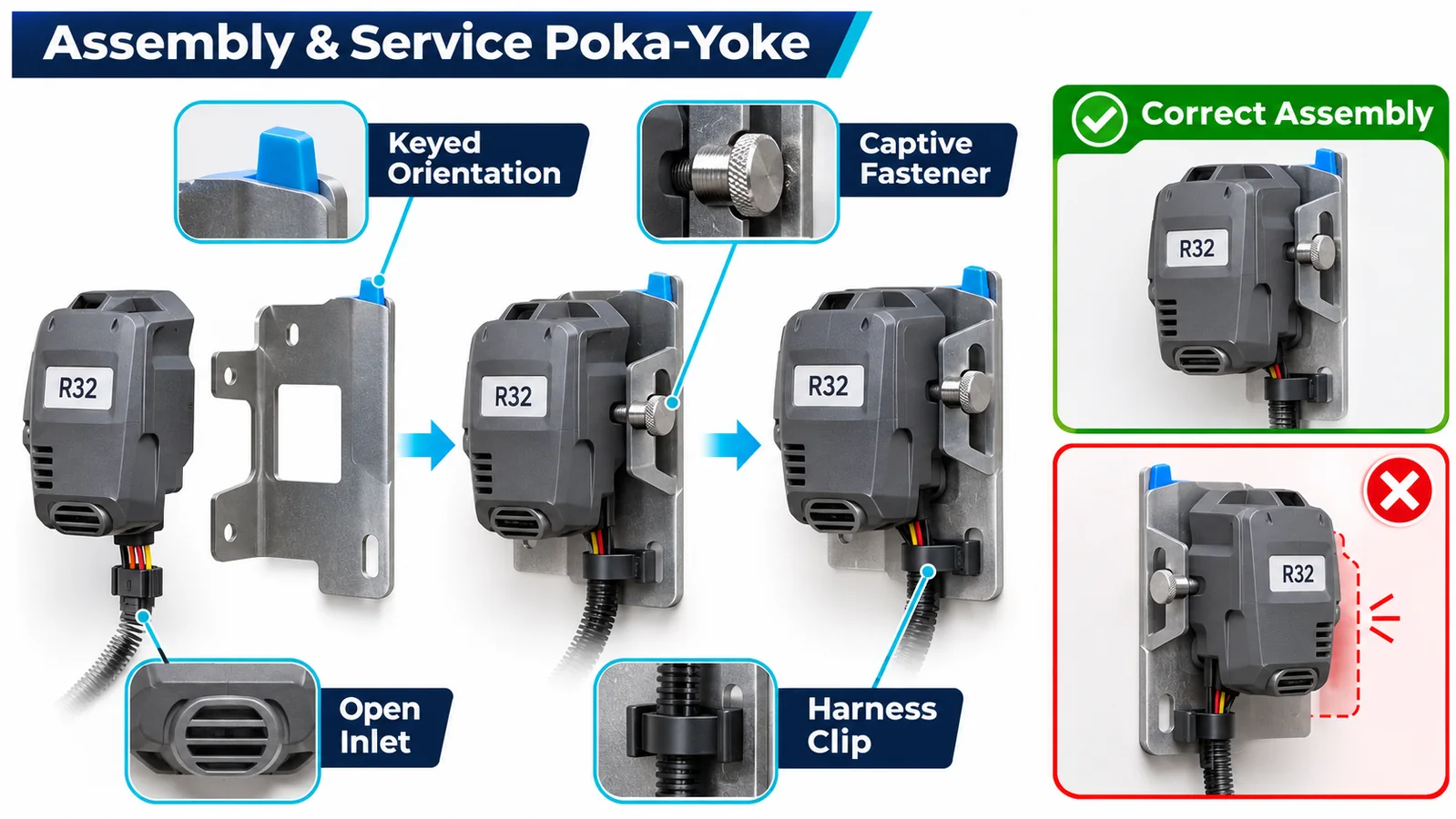
If multiple refrigerant variants share the housing, mechanical keying, distinct part control and electronic verification can work together. Do not rely on color alone. The work instruction should identify the exact part, gas, orientation and inspection points.
Design for automated or simple manual inspection. A visible datum mark, exposed label, barcode, connector-latch window and clear inlet keep-out make errors easier to catch. Hidden fasteners or inaccessible labels weaken line checks.
Prototype with production operators and service technicians. Watch how they hold the sensor, route the cable and start fasteners. A design that requires three hands or blind alignment invites shortcuts. Modify the bracket so the correct assembly is the easiest assembly.
11. Support Safe Service Replacement
Service access must not require bending refrigerant tubing, moving a drain, removing unrelated safety components or pulling the harness. Reserve hand, tool, connector and extraction paths. Ensure the sensor cannot fall into the cabinet after fastener removal.
Define whether the bracket remains with the equipment or is replaced with the sensor. A reusable bracket needs durable datums and joints. A sensor-bracket service assembly can preserve orientation but needs controlled part identity and may increase cost. Choose deliberately.
Post-replacement checks should confirm part/gas variant, bracket seating, torque or latch, connector engagement, harness retention, inlet clearance, detector validity and any required system function. Internal self-test does not prove the bracket returned to the qualified gas field.
Repeated replacement testing should use aged parts and realistic access. Check thread wear, coating damage, clip retention, harness length and technician error modes. Update instructions with photographs of the final accepted route.
12. Integrate the MH-Z1542B-R32 Conservatively
Winsen lists the MH-Z1542B-R32 as an NDIR R32 refrigerant sensor with a UART-related integration path in current product information. The exact dimensions, active inlet geometry, mounting restrictions, supply, protocol, environmental limits, response, diagnostics and qualification evidence must be confirmed using the controlled current datasheet and project documents.

Before freezing a bracket, obtain the mechanical drawing with datum scheme and tolerance, connector specification, allowed orientation, inlet keep-out, maximum mounting loads, vibration/shock limits, water/condensation restrictions, approved materials and cleaning guidance. Confirm whether any membrane, cover or shield is part of the supplied, qualified configuration.
Do not measure a web image to create CAD. Do not assume two visually similar variants share dimensions or calibration. Control the exact model and revision in the equipment bill of material and supplier change process.
The detector supplier’s component information must be combined with the HVAC OEM’s gas-transport, environmental and service validation. The bracket is the interface between those evidence sets.
13. Validate the Bracket as a Coupled Assembly
The verification plan should include:
| Domain | Key questions |
|---|---|
| Gas exposure | Does the final inlet position respond across covered release points and airflow states? |
| Dimensional | Do tolerance extremes preserve location, inlet keep-out, connector and service access? |
| Vibration/shock | Do modes, fasteners, joints, housing and harness remain stable? |
| Water | Do rain, condensate, overflow, cleaning and freeze/thaw drain without blocking or damage? |
| Corrosion | Do materials, finishes and joints remain functional after relevant exposure? |
| Assembly | Can production build the correct orientation and route repeatedly? |
| Service | Can the detector be replaced and verified without disturbing adjacent systems? |
| Controls | Are identity, connection, validity and fault states detected after installation? |
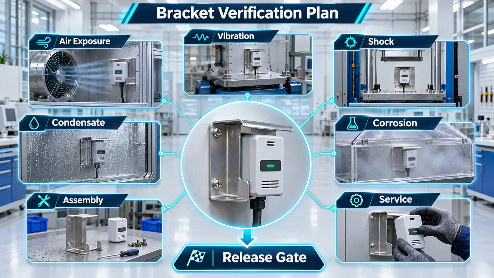
Sequence tests to reveal interactions. For example, vibration may loosen a joint that then retains water; corrosion may change grounding and fastener torque; service cycles may damage coating before salt exposure. After conditioning, repeat dimensional inspection, diagnostics and gas-response tests.
Use production-intent detector housings, fasteners, harnesses, panels and finishes. Record revisions, torque, fixture, environment and failure criteria. A bracket test coupon is useful for material screening but cannot replace the final assembly.
14. Control the Bracket in Manufacturing
Release drawings should identify safety- or function-critical characteristics: datums, mounting position, orientation features, inlet keep-out, drain slope, shield openings, fastener type/torque and harness retention. Link them to process controls and inspection methods.
Verify forming fixtures and springback. A bracket can meet flat-pattern dimensions while the final angle places the inlet too close to a wall. Use gauges or vision inspection for the functional output. Track process capability and react before assemblies reach the response boundary.
Control substitutes. A different fastener finish, clip, foam, coating or harness can affect corrosion, vibration or gas exposure. The change review should ask whether any function or validation result is touched. Supplier drawings and control plans must carry the same critical features.
End-of-line checks should confirm part identity, orientation, retention, connector, route and unobstructed inlet. Periodic audits can include functional exposure using a controlled method. Preserve photographs or digital inspection data for high-value configurations if practical.
15. Engineering Release Checklist
Confirm before release:
- The detector location comes from gas-transport evidence.
- Stable equipment datums define inlet position and orientation.
- A documented three-dimensional inlet keep-out survives tolerance extremes.
- Shields, screens or membranes are included in response validation and change control.
- Modal analysis and hardware testing cover equipment and shipping excitation.
- Fasteners and joints retain stiffness through environment and service cycles.
- The full tolerance stack protects gas, connector, drainage and tool functions.
- Water flows away from inlet and connector under realistic exposure.
- Materials and finishes are compatible as a galvanic/corrosion system.
- Assembly poka-yoke prevents wrong orientation, part and route.
- Replacement returns the detector to the qualified configuration.
- Coupled environmental tests are followed by gas-response verification.
- Manufacturing controls measure functional characteristics, not only component dimensions.
- Exact detector model, revision and controlled documents are frozen.
If a requirement depends on a drawing note that cannot be inspected, redesign the characteristic or the inspection method.
16. Review Failure Modes Across the Product Life
Run a bracket-focused design failure-mode review with airflow, mechanical, electrical, manufacturing, quality and service participants. Consider not only fracture but functional loss: inlet blocked by shifted insulation, detector rotated during replacement, connector side-loaded, water retained behind a shield, corrosion products entering the inlet, fastener preload lost, bracket resonance changing the module position, or a wrong gas variant fitting the same pattern.
For each mode, identify prevention, detection and evidence. A locating pin prevents rotation; a line inspection may detect it; a gas-response test verifies the functional result. Do not assign a low occurrence simply because no field data exist for a new platform. Use analogous assemblies, process capability and environmental testing to justify the rating.
Include shipping and installation. Pallet shock, cabinet lifting, vibration during road transport and panel handling can load the bracket before the first operating hour. Inspect packaged-equipment tests for permanent displacement, loosened joints and harness contact. Installation screws or field accessories near the detector should have controlled lengths and routes.
Include maintenance aging. Filters, coil cleaning, drain service and panel removal can move nearby foam or cables. Cleaning chemistry can attack coating or label adhesive. A replacement part may use a supplier-revised housing. Define service inspection points and supplier change-notification requirements that address these modes.
The review should generate specific verification or control actions, not only a risk number. Assign owners and closure evidence. Revisit the analysis when the limiting test changes, a field pattern appears or the bracket/sensor interface changes.
17. Use Prototype Stages Deliberately
Early prototypes can use adjustable rails or instrumented brackets to explore location. Mark these as development hardware and record coordinates, because a taped sensor or machined fixture may not reproduce sheet-metal shielding, vibration or drainage. The purpose is to learn the gas field and sensitivity, not to create release evidence.
The next stage should use representative forming, finish, fasteners and harness. Test assembly sequence and service access with production operators. Measure the actual inlet position and mode shapes. Use controlled releases to compare the representative bracket with the development fixture. Differences are design information, not test noise.
Qualification hardware should match the released tool, detector revision, cable, connector, panel, seal and firmware. Freeze configuration before the final matrix and control any deviation. If hand-built parts remain, justify why their functional characteristics represent production extremes.
Pilot production then tests process capability. Use gauges or vision checks on the critical outputs and audit gas response on selected units. Watch for unexpected installer workarounds, clip variation, coating buildup or cable-length effects. Feed findings into the drawing and work instruction before volume ramp.
This staged approach reduces the risk of qualifying a beautiful prototype that the production process cannot reproduce. It also preserves useful exploration while keeping a clear boundary between concept evidence and release evidence.
Abschluss
An R32 detector bracket translates system-level validation into mechanical repeatability. Its geometry affects gas exposure; its stiffness affects durability; its surfaces affect drainage and corrosion; and its features affect assembly and service errors. Treating the bracket as part of the sensing function produces a design that can survive real production and field conditions.
For an engineering review, provide the refrigerant, detector model/revision, application and orientation, candidate location, surrounding CAD, airflow states, vibration sources, water/cleaning exposure, materials, harness route, service plan, annual volume and target market. That package allows the detector supplier and OEM team to resolve bracket requirements with controlled evidence.
