
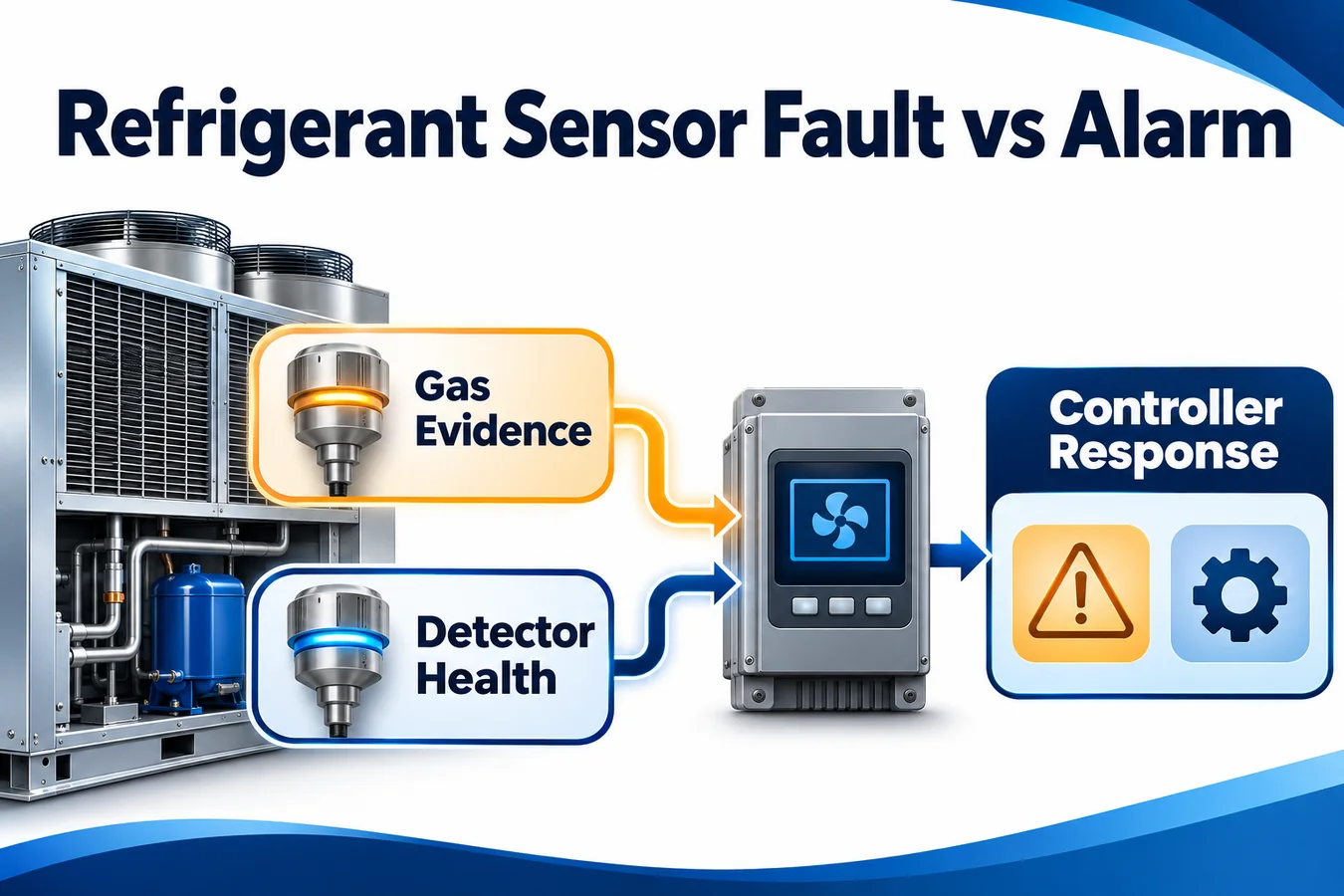
A refrigerant alarm reports that the detection system has recognized the event defined by its approved design. A sensor fault reports that some part of the detection function has failed or can no longer establish that its output is trustworthy. The same appliance response may be required for either condition under the equipment design. The diagnostic record still needs to retain which condition occurred, what evidence was available and how the system reached its current state.
The practical question behind refrigerant sensor fault vs alarm is whether a controller, service display and event history will tell the same story after a disconnected harness, a sensor restart or an actual alarm followed by a loss of communications. A design that reduces every state to a single Boolean at the interface can leave the appliance with the right output command and the wrong diagnostic explanation. Model the observation and its quality separately before mapping either to the equipment response.
Assign one owner to each interpretation
Describe the sensing element or module, the receiving controller, any intermediate gateway and the service interface. For each, identify what information it originates and what information it forwards. A sensor may originate a measurement, an internal diagnostic or a discrete alarm. The controller may originate loss of communication based on its receiver clock. A gateway may originate a gateway connection error while retaining a correctly received earlier equipment event. The operator display should preserve those source distinctions.
Begin with exact part and revision information from both ends of the interface. Write down which device owns the alarm decision, whether the interface provides raw data, and how the receiving controller detects a fault. Define the result if a status flag and a numeric value disagree. Where the supplier contract leaves an output combination undefined, refer it for resolution and classify the observation as indeterminate in design review. A compatibility assumption should have an owner, a revision and evidence before it reaches the service code.
The examples below assume a controller reading a module that can communicate a validity state and an alarm indication, with a controller-side timer for receipt. A discrete interface can follow the same diagnostic structure to the extent its signals support it. Record which failure modes it can distinguish and which must share an unavailable category. These illustrative states describe evidence and diagnostic ownership. The equipment program defines the physical responses.
Use a matrix that permits simultaneous conditions
Keep health and alarm evidence as separate fields. Define current validity, alarm evidence, observation freshness and a record of prior alarms with their timestamps. Design every consumer of these fields, including service software, to handle a prior alarm and a current fault at the same time. A single display label can prioritize a message, while the event details expose both conditions and their order.
| Evidence received by controller | Current diagnostic interpretation | Record to preserve | Qualification question |
|---|---|---|---|
| Fresh valid report, no alarm indication | Available with no current alarm indication | Last accepted sample or state and time | Can a later invalid report change availability independently? |
| Fresh valid alarm indication | Alarm observed | First observed time, source and applicable state or value | Does the record survive a subsequent communication loss? |
| Explicit internal fault | Detector reported a fault | Exact supported fault reason and observation time | Can service distinguish this from the controller losing contact? |
| Last good report aged beyond accepted limit | Current state unavailable | Last accepted report and age at the transition | Can frozen frames keep the appliance in an available state? |
| Startup or declared warm-up | Monitoring readiness pending | Reset context and entry time, where available | Can a default numeric value masquerade as an accepted sample? |
| Alarm followed by invalid or missing data | Prior alarm remains recorded and current coverage is uncertain | Both events in observed order and source evidence for each | Can recovery or display prioritization erase either event? |
| Contradictory or unsupported status combination | Interface state indeterminate | Raw status and interface revision, where supported | Does the receiver have an explicit, tested interpretation? |
Certification criteria and the equipment design govern the response when monitoring is lost or a refrigerant event is recognized. UL Solutions describes self-test and appropriate fail-safe system response in its discussion of the fourth edition certification requirement decisions. The diagnostic matrix gives engineers and service teams a way to distinguish the causes that entered the equipment’s reviewed logic. UL Solutions overview of updated refrigerant detection system requirements
Distinguish a current alarm from a retained alarm
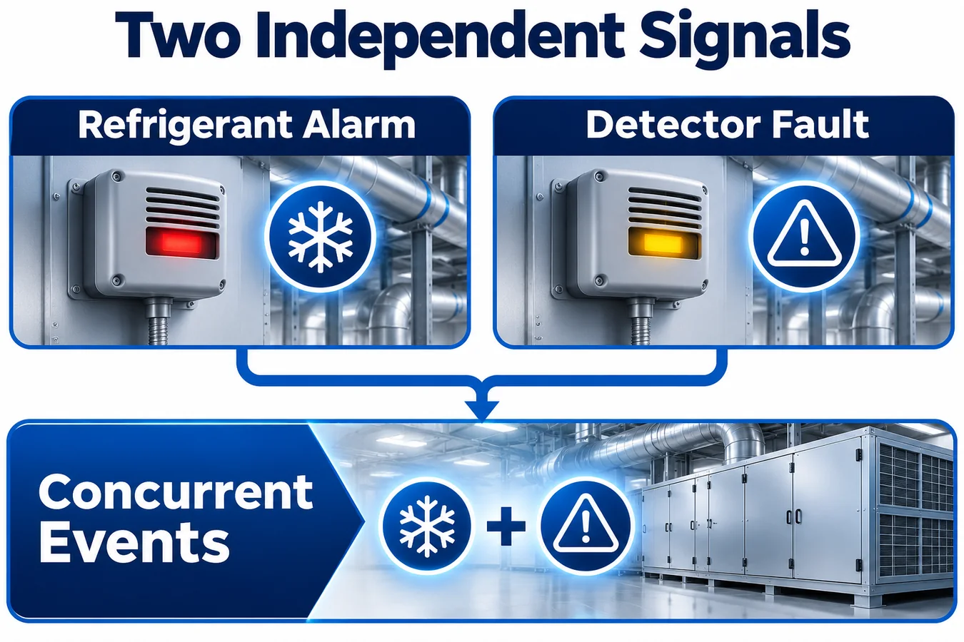
An accepted alarm event is evidence about a particular observation or interval. A retained alarm record preserves that event after the current input has changed. Specify whether the interface can explicitly report that the alarm indication cleared, whether the controller can confirm the clearance from valid data and how the certified equipment logic manages its own latch. Diagnostic history, active service display and equipment latch each answer a different question.
If the module goes offline while its last accepted indication was an alarm, a service screen can report that alarm in history and separately show that the current input is unavailable. A screen that displays only the last value leaves the operator guessing whether the reading is live. Conversely, replacing the event with a communication error can hide the original sequence. Pair each displayed value with an age and quality when those details matter for interpretation.
Test the reverse ordering too. Suppose a controller declares the sensor unavailable and the next valid report contains an alarm. The record should identify the gap and the first observed alarm after it. The actual event might have begun during the gap. The system can state when it saw the report and qualify the unobserved interval. That distinction matters when comparing a returned unit’s controller log with another device that continued reporting independently.
Define freshness from the acquisition boundary
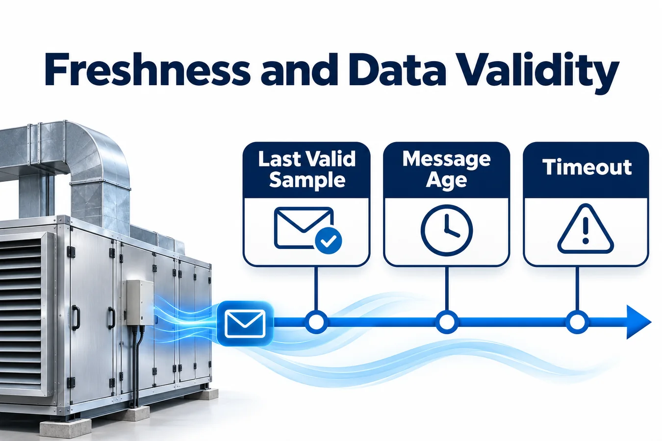
A valid checksum establishes integrity of the received frame under the interface design. Freshness concerns the state represented by that frame. If a sensor or gateway can retransmit an earlier frame, the controller needs an agreed indicator for a new acquisition or an explicit limit on what can be inferred from reception. Use the supplier’s documented semantics for a sequence number, timestamp or freshness bit. A packet counter generated by a gateway may describe transport activity while providing no direct evidence of a fresh sensor acquisition.
Use a monotonic receiver time base for local elapsed times. Log device time as an additional field where the protocol supports it and where rollover or reset can be interpreted. Define how duplicate, out-of-order and delayed frames affect the time of the last accepted sample. An unchanged numeric value can be legitimate across many acquisitions. A duplicate sequence value can also be legitimate under a polling design. Write the acceptance rule against the specific protocol, including the scope and rollover behavior of any counter.
In an illustrative trace, a controller receives fresh reports through the beginning of a run. The data source then freezes while an intermediate device continues sending frames. A receiving controller that records only bus arrival still appears connected. A receiver that checks acquisition freshness can mark the information unavailable when it ages out. Preserve the most recent accepted observation as historical context. Use the equipment’s approved timing and response for actual operation and derive test stimuli from the timing allowances and behavior of the chosen interface.
Handle restarts and initialization as explicit states
A sensor reboot can produce a gap, a reset reason, a warm-up indication or a temporarily repeated default value depending on its documented behavior. A controller reboot can also lose volatile reception history while the sensor continues sending current data. Specify what each endpoint can know during initialization. Define which configuration, freshness and self-test evidence must be present before the controller marks monitoring available.
For an intermittent power problem, repeated startups can resemble a stream of normal status if the controller counts every early frame as valid. Exercise the complete startup exchange while injecting brief interruptions at different points. Record which evidence survives a sensor-only reset, a controller-only reset and a shared power interruption. Check how the system reconciles a known prior alarm record with the new session and what the service tool can show if a reset removed volatile state.
A warm-up state should have a clear entry cause and a documented route out. If a module never becomes ready, the service record should distinguish extended initialization from a device that reached readiness and later reported an internal diagnostic. Which details are available depends on the interface. Use an explicit unknown where the receiver has only a gap and cannot distinguish reset from disconnection.
Separate supply symptoms from communication symptoms
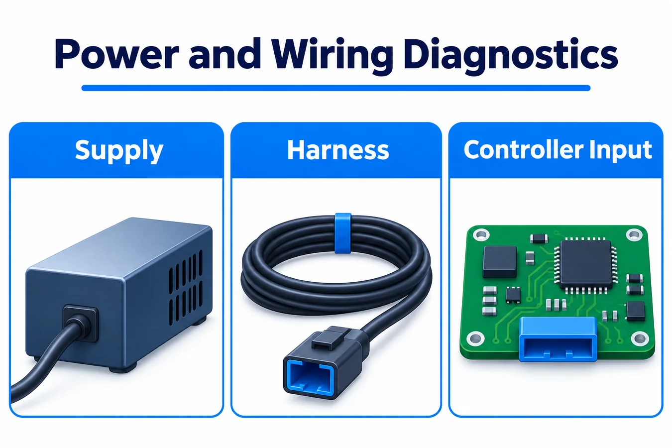
Loss of messages can reflect connector separation, a sensor-side supply dip, receiver failure, interference or a protocol mismatch. Record the observed condition at the owner that saw it. A controller can establish that valid reports stopped reaching its input. It can name a cause such as a measured supply interruption only when there is suitable independent evidence. Avoid deriving a sensor replacement instruction from one receiver timeout alone.
Capture the supply at the module connection during a reproduced failure when your laboratory setup permits it. A measurement at the controller supply entry may miss voltage loss through the harness or connector. Record whether the module, the receiving interface and any intervening equipment share a reference or power path. Use synchronized traces of power, communications and module restart indicators to distinguish a sensor-side restart from a receiver or gateway restart.
For a discrete or relay interface, document the behavior when either endpoint loses power. Evaluate the signal with the wire open, shorted as applicable to the circuit and under disconnected or mismated connector conditions included in the program. If a single contact state can result from multiple causes, describe the available controller observation precisely. Any additional discrimination needs supervised wiring, additional telemetry or another documented interface feature evaluated with the appliance.
Preserve simultaneous channel results in multi-sensor systems
Identify the detector channel by a stable physical location and logical address. When one channel reports an alarm and another becomes unavailable, retain each result under its own identity. Record the aggregate equipment status separately. If the architecture associates channels with separate coils or compartments, that association belongs in the controlled configuration used by the service tool and event export.
Define the diagnostic response to swapped connectors, duplicate addresses and sensors returning under an unexpected identity after replacement. A successful polling cycle can reach the wrong device. When the protocol provides identity information, compare it against the configured position or address mapping and preserve discrepancies. Where hardware has no identity field, use the configuration and commissioning procedure to establish how the mapping can be verified.
If controllers share a gateway, distinguish an unavailable gateway from multiple independent sensor failures. The gateway may itself be the first point that can show which channels stopped reporting. Log at the equipment layer where possible and label the point where each state was inferred. This makes it possible to reconstruct a common interruption without inflating the apparent number of component faults.
Store enough context to reconstruct the sequence
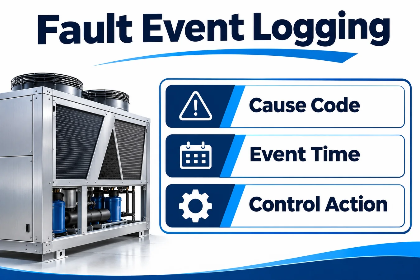
A useful event includes device and channel identity, firmware and configuration where available, observed and recorded times, prior state, new state and evidence source. Include the original fault code or status bits and any relevant data age. If the numeric value was valid at the time, record it with its units and validity. If a timestamp comes from an unsynchronized device, preserve that fact and use a controller timestamp or event ordering field alongside it.
Design the record for the first failure and for repeated failures. Log meaningful transitions and keep counters for recurrence where this helps diagnose an intermittent harness. Use a retention policy sized around the service question. A high volume of repeated communication warnings should leave earlier evidence accessible, particularly the first alarm or the first transition into unavailable monitoring. If records can overflow, preserve an explicit indication that older evidence was lost.
Consider what happens during abrupt power loss. Verify which records are persisted before a restart and what can be reconstructed from reset data on the next boot. Retain implementation metadata such as a reason code dictionary or firmware mapping so tools can decode logs from units already in the field. A compact summary can give a technician the event order and reference the original fields for a detailed OEM investigation.
Keep acknowledgment, recovery and history independent
A technician acknowledging a message establishes that someone has seen it. Restoring a connector may return transport. A qualified stream of current valid data can establish availability under the approved design. These actions can occur minutes apart or in the opposite order. Give each its own recorded event and avoid using a screen action to overwrite input health or erase the cause history.
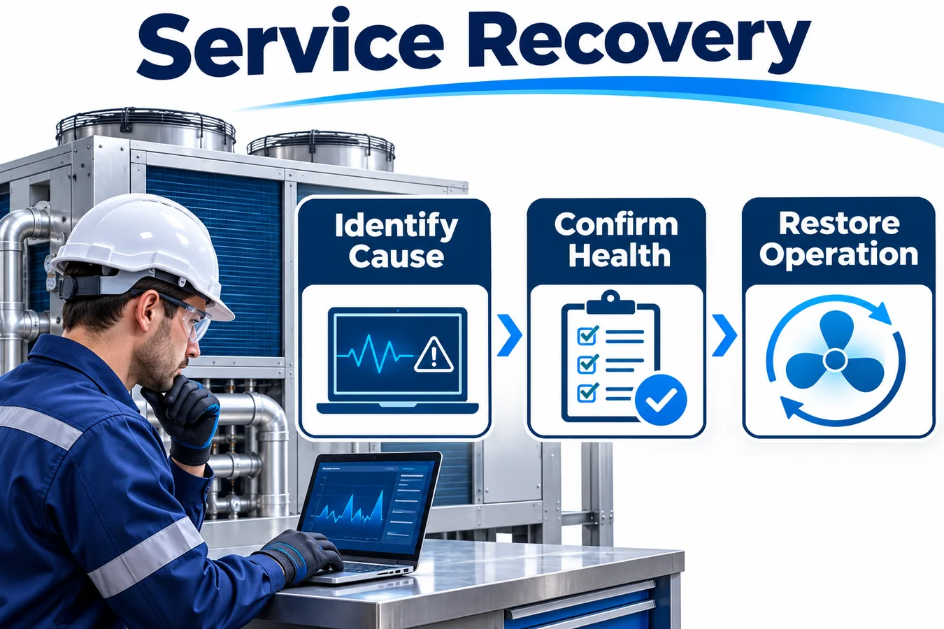
After an authorized replacement, compare the module part and revision with the equipment configuration and run the applicable verification procedure. Confirm the receiver identifies the correct channel and sees the expected startup and valid states. If a prior event remains in history, the service interface should display it as a retained event with its timestamp and show current availability separately. Capture any unresolved causes before closing the service record.
Define how recovery behaves when faults are intermittent. Briefly restored contact may satisfy a low-level link indicator while the receiver still lacks a valid measurement or verified self-test status. Use separate transitions for communication and qualified sensing where the interface exposes that distinction. Verify that repeating the event within a service visit produces an understandable sequence, including any repeated startup or partial restoration.
Qualify the diagnostic contract with fault injection
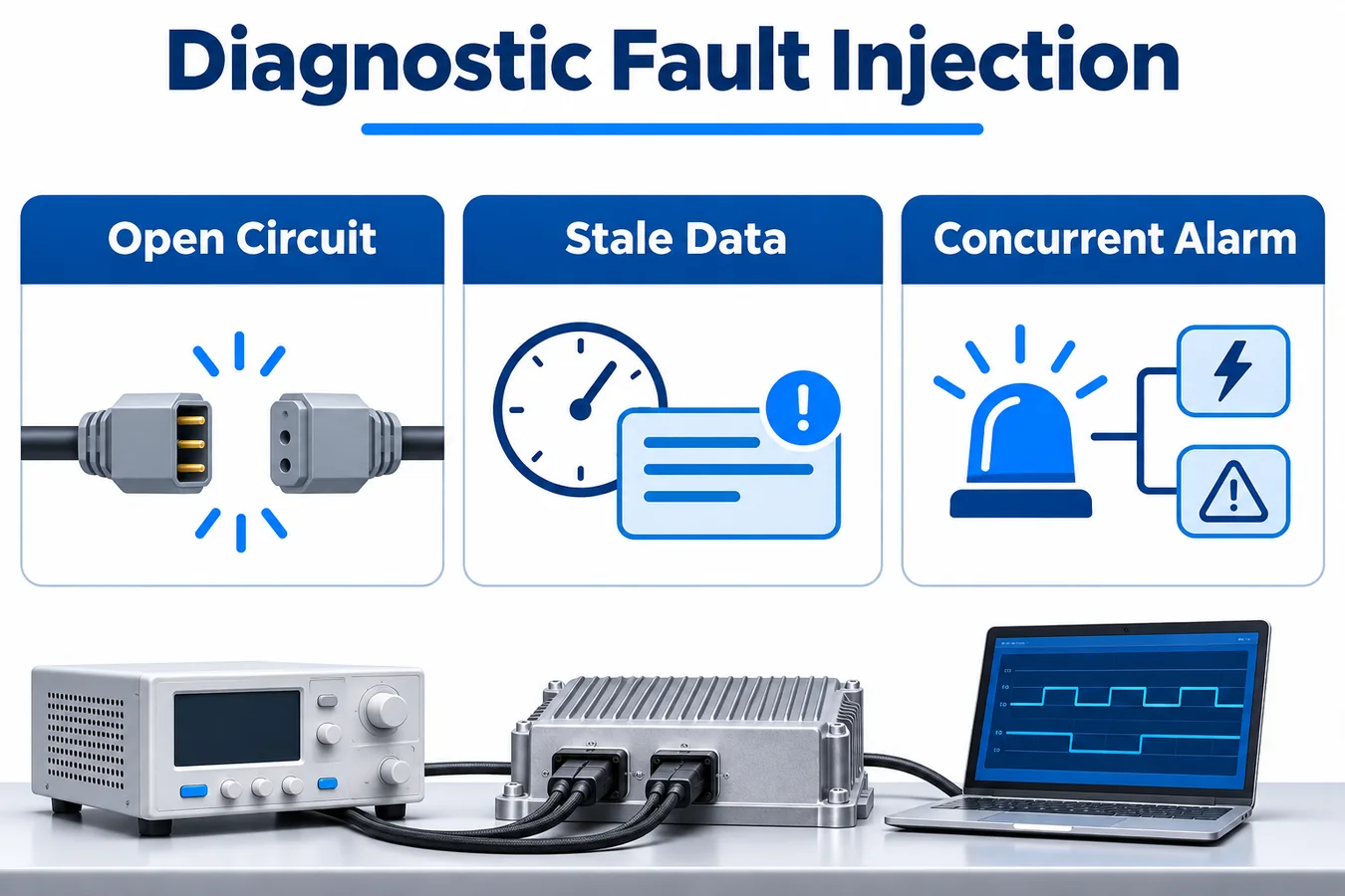
Run scripted interface cases and complete-appliance cases. A test bench can control frame contents, timing and contradictory fields precisely. The assembled appliance can show how wiring, power behavior, the actual controller and service records interact. For each case name the injected condition, expected state, expected evidence and separately defined equipment behavior. Save the trace and the visible service output from the same run so either can be compared to the specification.
| Injection | Record to inspect | Example diagnostic acceptance check |
|---|---|---|
| Stop valid reports while the last observation was clear | Last valid state, age and controller observation | Availability changes and the previous value is marked historical |
| Repeat an earlier valid frame through a working gateway | Receiver arrival and acquisition indicator | Transport activity is distinguished from current sensing evidence where supported |
| Annunciate an alarm, then disconnect the sensor link | Alarm time, fault time and service display | Both causes are retained with the correct observed order |
| Interrupt power at the module and leave the receiver powered | Sensor startup and receiver event log | Reset evidence is classified according to the interface contract |
| Restart the controller while an alarm record exists | Persistent history and newly acquired state | History remains attributable to the original session |
| Restore contact with a wrong or unready module | Connection state, configuration or readiness fields | The display reflects the remaining evidence gap |
Run boundary cases around the documented timing and startup behavior of the selected hardware. Include delayed delivery, counter rollover and controller resets where relevant. Check how the display renders two current issues, including any prioritization. Validate event exports as well as on-device screens. A log schema can be technically complete while an export silently omits the older alarm from the service report.
Laboratory component evidence and completed-system evidence have distinct scopes. Intertek describes testing that can be performed on the refrigerant sensor independently and identifies the need for final assembly testing of the refrigerant detection system. Link the test cases to the applicable appliance evaluation plan so each result is used at its intended scope. Intertek overview of refrigerant leak detection system evaluation
Put the evidence contract under revision control
Include the signal or register map, defined states, freshness semantics, test evidence and service wording in the release package. Tie each message displayed by the equipment to the observation that supports it. When adding a code, document the behavior of older firmware and service tools encountering it. A receiver should have a reviewed interpretation for unsupported status patterns rather than letting them fall into its ordinary valid state.
Treat an alternate supplier module, firmware change or gateway update as a potential interface change even when the connector and nominal signal type remain the same. A module can change when it clears a status bit on startup. A gateway can change which frame it repeats after a timeout. A service tool can change what it calls an offline sensor. Evaluate changes through the same interface cases used for release and keep the revision identifiers with the results.
Prepare a short decision sheet for each variant. It should describe how the controller recognizes available sensing, observed alarm, explicit fault, stale data and recovery. List ambiguities the interface cannot resolve and what service evidence could resolve them. That sheet gives reviewers a way to trace each outward-facing message back to a justified observation.
Consider a returned appliance whose service export contains the words “sensor failure” at three points overnight. The export shows the same controller channel each time and a reboot marker before one occurrence. At the bench the replacement detector can communicate. The existing evidence supports a recurring symptom at that channel and one observed reset. It leaves open whether the detector itself failed. Use the controlled reason code dictionary to see whether the controller reported a timeout, a sensor self-test result or an invalid value. If the same label covers all three, the translation table is a defect in the diagnostic handoff even if the equipment response was correct.
A useful release check is to give the service and firmware teams the same trace and ask them to classify it independently. Ask them to identify the earliest confirmed event, the observation that supports it and what remains unknown. Include at least one trace where a correctly received fault message and a missing report require different codes. Compare their answers with what the appliance actually exports. When the trace has a gap, verify that the service tool preserves the gap and its boundaries. If a conclusion depends on an undocumented assumption, resolve it in the interface specification and repeat the check with the updated diagnostic wording.
Candidate module for an OEM interface review

Winsen publishes a ZRT512C-A refrigerant detection module family. Consider the exact ZRT512C-A configuration as a candidate after the supplier confirms the intended refrigerant and supplies the controlled interface description. Request ordering code, firmware identification, supported fault indications, initialization behavior and any acquisition freshness semantics. Compare those documents and the actual sample behavior with the controller evidence contract. Winsen ZRT512C-A product documentation
Frequently asked questions
Can a fault and an alarm appear at the same time? The architecture can retain a prior observed alarm and report a current fault. Multiple channels can also supply distinct observations concurrently. Explain on the screen whether the alarm is current, retained or time-qualified by unavailable data.
What does a zero measurement mean if the module reports a fault? Its meaning depends on the documented data validity rules. If the reading is invalid, preserve the raw value as diagnostic evidence if useful and show its quality. A display that simply presents zero can suggest an available current measurement where the controller has none.
Is a disconnected detector the same as a failed detector? A receiver may observe the same timeout for either. Use supported evidence such as power measurements, bus activity or device-reported states to refine the diagnosis. If a timeout is the only evidence, the service message can describe lost communication and identify the affected channel.
Can a technician clear the fault by acknowledging it? Acknowledgment can clear or change the presentation of an acknowledged message under the service design. Recovery of sensing is a separate result based on the required state evidence and procedure. Keep a record of both transitions.
How much raw data belongs in the service log? Capture enough to support the classification and event order. An event summary with source, time, quality and reason code can usually point to a short diagnostic capture when more detail is required. Match retention and access to the needs of the equipment service program.
Request an OEM diagnostic interface review
Share the intended module ordering code, controller and gateway revisions, interface specification, state table and service message list. Include example traces for warm-up, alarm, missing data and fault recovery, along with any known revision differences. Identify the equipment program and whether testing is at component, controller or full appliance level. These inputs support a review of evidence ownership, ambiguities in the proposed codes and a fault injection matrix that can be traced to the released equipment behavior.
Review the ZRT512C-A product listing Và submit the equipment details for an OEM integration review.
