
An evaporator coil can carry the refrigerant, the furnace can own the blower, and an outdoor board can own the compressor. In a split system, those functions meet at wiring interfaces that may have been designed and released by different teams. An R454B sensor furnace coil project should therefore define the approved assembly, its release paths, and the authority of each controller before selecting a detector or writing a sequence.
A useful engineering deliverable is a traceable combination matrix. Each row ties a furnace, coil, outdoor unit, cabinet orientation, and control architecture to a detector location and installed mitigation evidence. The same model name can cover multiple physical arrangements. An apparently small change such as a drain pan, furnace adapter, or blower program can change the evidence that applies to a row.
1. Establish the combination boundary
Start with the equipment release identifiers for the indoor coil, furnace, outdoor unit, and factory or field kit. Add the installation configurations and line set constraints used for the combination. On a separate layer, identify the equipment that participates in the mitigation function. Include the thermostat and zone equipment when their demands or airflow settings can affect the physical result, even if their interfaces carry ordinary comfort signals.
For each approved combination, ask which team owns the cabinet geometry, which team owns the blower program, and which team can change compressor enable behavior. A coil engineer may know where a release can travel without knowing how the furnace reacts during ignition or a limit event. A controls engineer may know the blower command path without knowing whether a new adapter creates a gas pocket. The combination review needs both views and an accountable owner to reconcile them.
Where an integral refrigerant detection system is part of the equipment certification, installation and equipment-specific instructions form part of the evidence. Use the applicable standard and certification basis for the target model and market. UL Solutions explains the relationship between the integral detection system, equipment evaluation, and manufacturer instructions. UL Solutions overview of integral refrigerant detection
2. Draw the complete furnace and coil stack
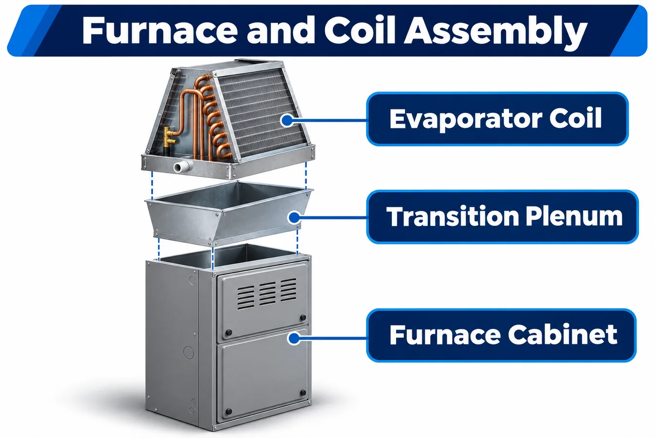
Draw a section from the return opening through the furnace, the transition, the coil casing and the supply connection. Show the installed gravity direction and the airflow arrow independently. Place refrigerant-bearing joints, slab edges, insulation, wiring penetrations, service doors and pan openings on the same drawing. Annotate places where drawings leave room for field variation, such as cabinet spacing, the depth of a mounting flange, or the position of an installer-supplied transition.
Identify the locations where the nominal cabinet outline hides functional geometry. A folded flange may retain a shallow pocket. A pan edge may create a divide between two slab bays. A door gasket may steer gas toward a drain route with the blower idle, while the same seam may draw air inward under a different pressure field. Turn each relevant feature into a testable question about gas arrival at a sensing inlet or movement into the connected air path.
Record whether each seam or opening is deliberately controlled. If the design credits a seal, drawing tolerances and service reassembly affect the credit. If the design credits exchange between two chambers, measure evidence of exchange at the boundary conditions that matter. An assembly section with pressure and transport annotations can carry those assumptions into procurement and service more directly than a detached sensor placement drawing.
3. Treat orientations as separate configurations
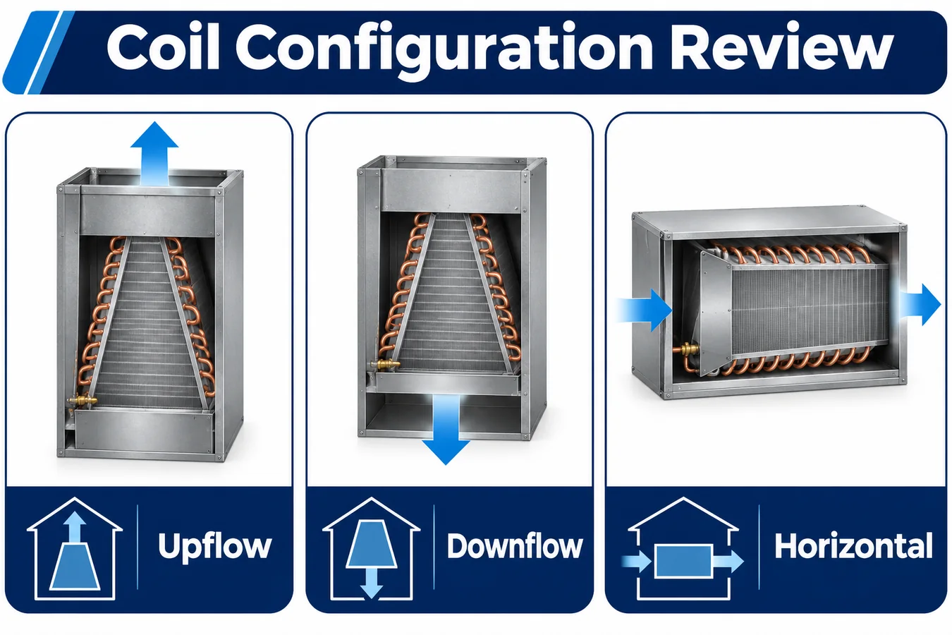
Review upflow, downflow, horizontal left and horizontal right separately for every coil offered in those configurations. A direction in the compatibility matrix is a particular construction. It includes the drain pan in use, which openings are sealed, the location of the access door, and any kit or relocation feature. An unoffered orientation stays outside the released matrix.
Compare each orientation with a common set of coil landmarks. For example, assign a persistent identifier to the distributor side and trace where it lies in each installation. This prevents a drawing label such as “bottom left” from being interpreted from the technician’s viewpoint in one sheet and from the airflow side in another. Apply the same convention to brackets and harness drawings so inspection can identify the correct assembly without inference from a mirrored image.
Manufacturer examples show why the distinction matters. The CVAVA instructions are for a cased R454B coil offered for upflow or downflow with an internal sensor and an external controller connected to the furnace. Another OEM manual documents sensor relocation for particular orientations on its own equipment. Treat each instruction as model-specific evidence of how an OEM controls geometry and assembly. CVAVA coil installation instructions · Carrier indoor unit installation instructions
4. Make the leak map useful for selecting a location
Group credible release points by both physical source and transport route. Consider the coil header, distributor and feeder region, return bends, connection compartment and field joints within the assessed boundary. Two release points can be physically close but separated by insulation or a pan edge. Conversely, several locations may share a well-defined route that can be challenged with a single justified test case.
Give each candidate location a transport hypothesis. A bracket in a pan-side pocket might sample gas reliably at rest but sit in a local clean-air stream when the blower runs. A position at a mixing point might perform well at steady flow but have delayed exposure when a cabinet sits idle. Compare observed arrival, repeatability, environmental exposure and physical access before choosing a location. A detector inlet with favorable gas transport still needs a mounting construction that supports consistent production and service.
Separate release-to-inlet travel from inlet-to-signal response. In a controlled laboratory trial, reference measurements near the sensing inlet and at selected cabinet landmarks can help interpret a delayed detector signal. If the inlet sees the challenge late, investigate the path, fixtures and cabinet state. If the inlet sees the challenge as expected but the controller responds late, inspect sensor behavior, sample validity and interface timing. This separation keeps a transport problem from becoming an arbitrary software timing change.
5. Test the blower states that change gas transport
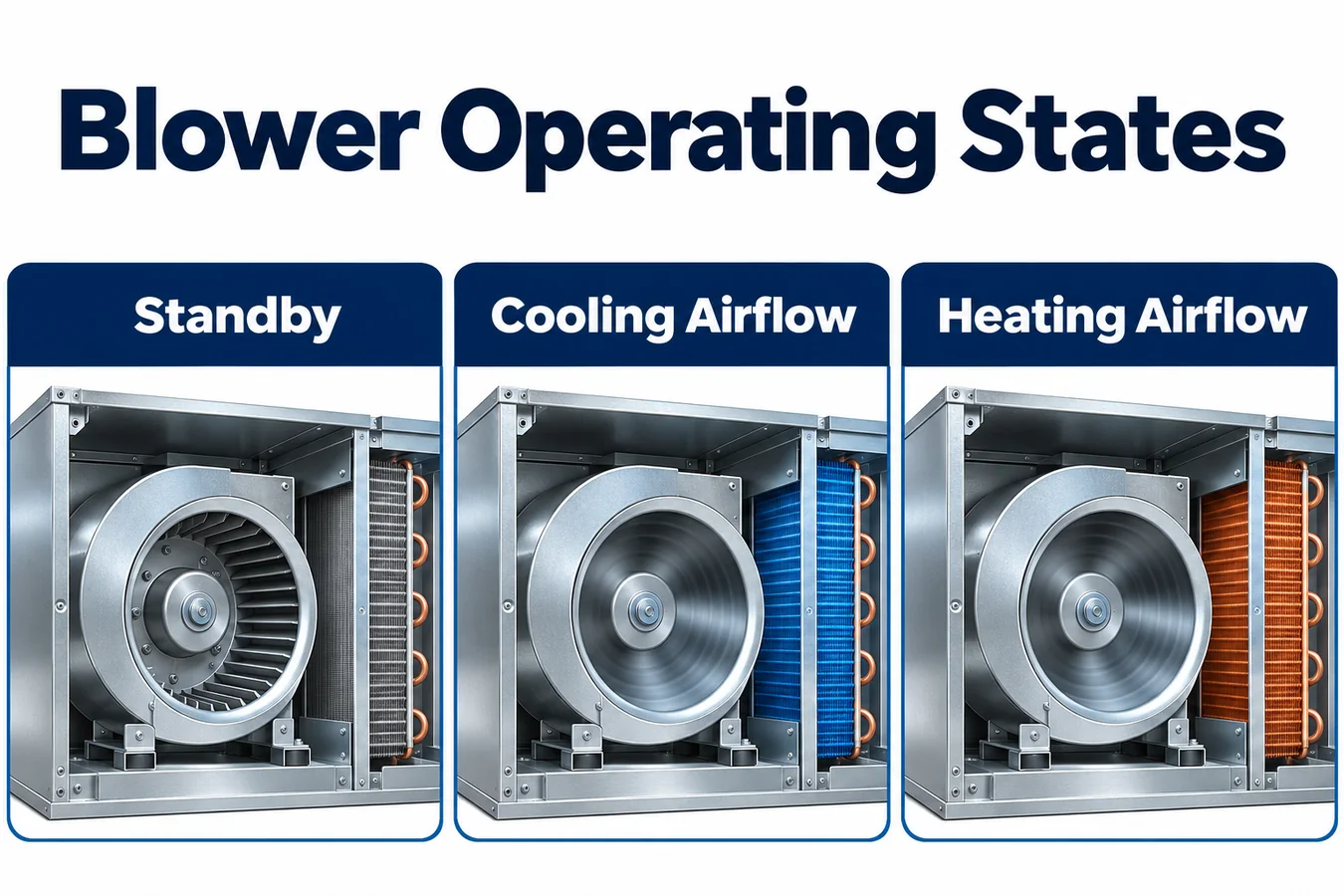
Create a table that distinguishes idle, fan-only operation, active cooling, a relevant heating call, transition out of a call and mitigation airflow. Include only states offered by the combination. For each row, record the actual blower operating mode, cabinet pressure conditions, and the outdoor and heat source requests present at the time of a detection event. A motor command can be active during a ramp while effective flow remains below its stabilized value.
Watch for mode changes that alter the preferred route. In the illustrative arrangement, a header-end pocket fills while the blower is idle. The early portion of the fan ramp clears that pocket and carries gas toward the slab exit. A test that covers only the two steady endpoints can miss a release that starts during the ramp and spends little time in either sampled area. Select transition trials using the mechanism they exercise, such as dilution at the inlet, redirection across a divider, or a temporary closure in an airflow path.
Include the external static range and relevant accessory settings in the matrix. A filter, zone panel or field duct configuration can change the relationship between programmed blower operation and measured airflow. State what was controlled in the fixture and what was measured. When sharing evidence between configurations, compare the air path and operating envelope as well as the fan command.
6. Assign authority at the board interfaces
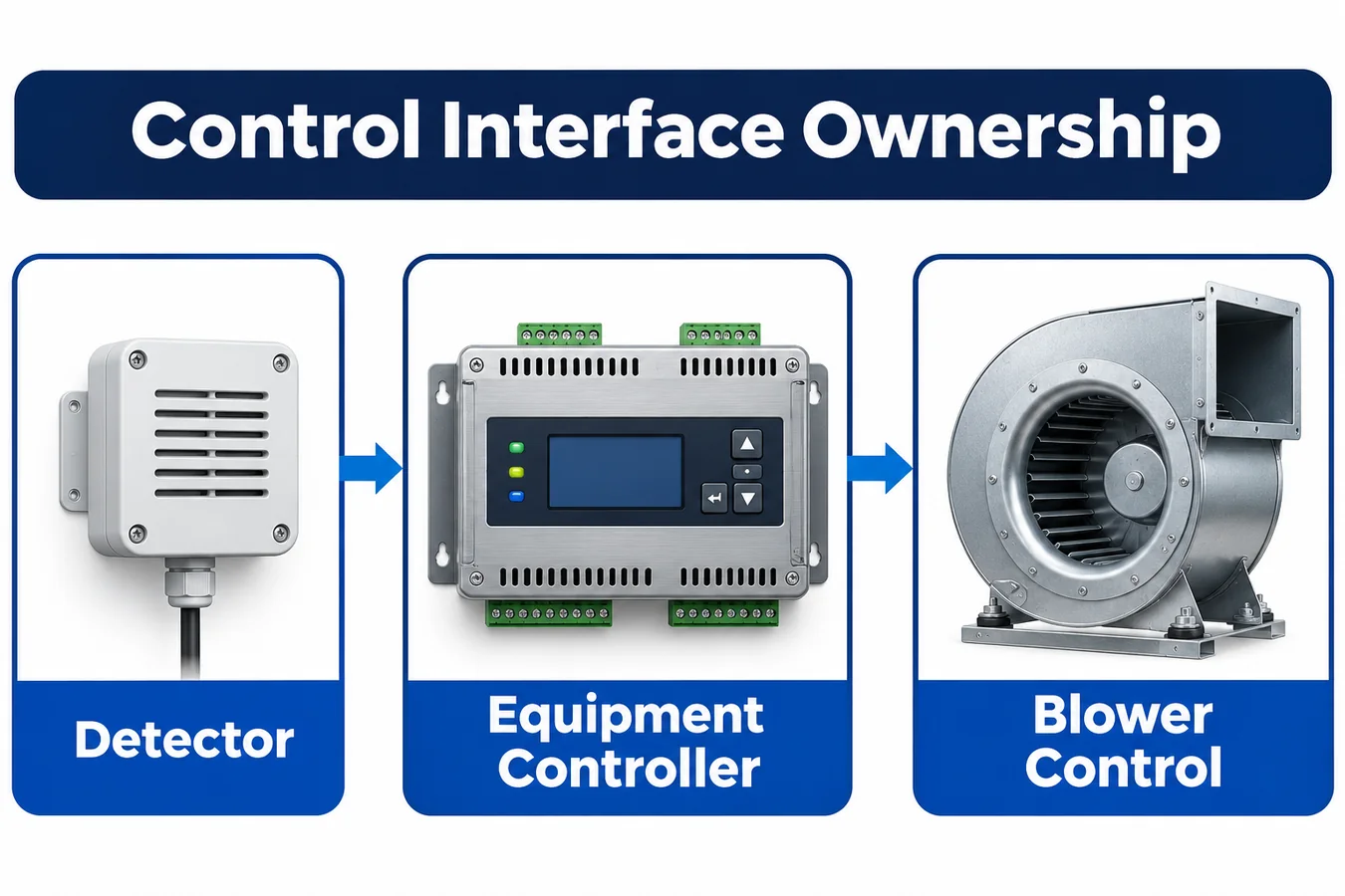
Map each interface by sender, receiver, asserted meaning, validity conditions and owner of the physical action. Separate detector indication from the control decision and from the actuator outcome. The furnace board can own blower behavior while an intermediary controller owns the decision to request it. A thermostat display may communicate the condition while the outdoor board owns the response to a compressor inhibit.
For wired demands, identify whether an interface reads a call, intercepts it, or issues a separate request. Record what a de-energized relay, broken conductor or power loss means at each receiving board under the actual wiring arrangement. For communicating platforms, record the message source, acknowledgment, stale-data policy and role of any discrete backup interface if the released design includes one. A terminal with a familiar name and a bus message with a familiar label both need evidence from the exact receiving firmware.
The CVAVA manual illustrates an architecture in which connection details differ between communicating and other arrangements. Use its drawings to see the types of interfaces an OEM needs to document. Base each product’s design on its released schematics, control specification and certification evidence. CVAVA coil installation instructions and wiring diagrams
7. Verify physical behavior when calls collide
An alarm can arrive while a gas heat call is already in progress, when the thermostat is starting cooling, or just as a blower post-run ends. For each relevant collision, put the expected sequence on a timeline. Include input acceptance, the furnace transition, mitigation airflow becoming effective and the status of the outdoor unit. Use the equipment’s approved response policy to define which requests are held, which can execute, and when each action is considered complete.
Preserve the furnace’s own combustion controls in the architectural review. Determine how the approved mitigation request interacts with ignition sequencing, an active limit response and furnace fault handling. Record behavior for any condition in which the furnace cannot provide the assumed airflow. If the architecture relies on a particular fan function being available during another furnace mode, bring evidence from that mode to the review.
For an illustrative test, begin with a valid heat request and record the actual furnace phase at event acceptance. Capture the board inputs and outputs alongside a physical indicator selected by the test plan. Repeat with the event already active when the heat request arrives. The same final indication may appear in both tests, while the output ordering and transient behavior differ. Compare the timeline with the released expectations for both cases.
8. Design the harness for assembly and service
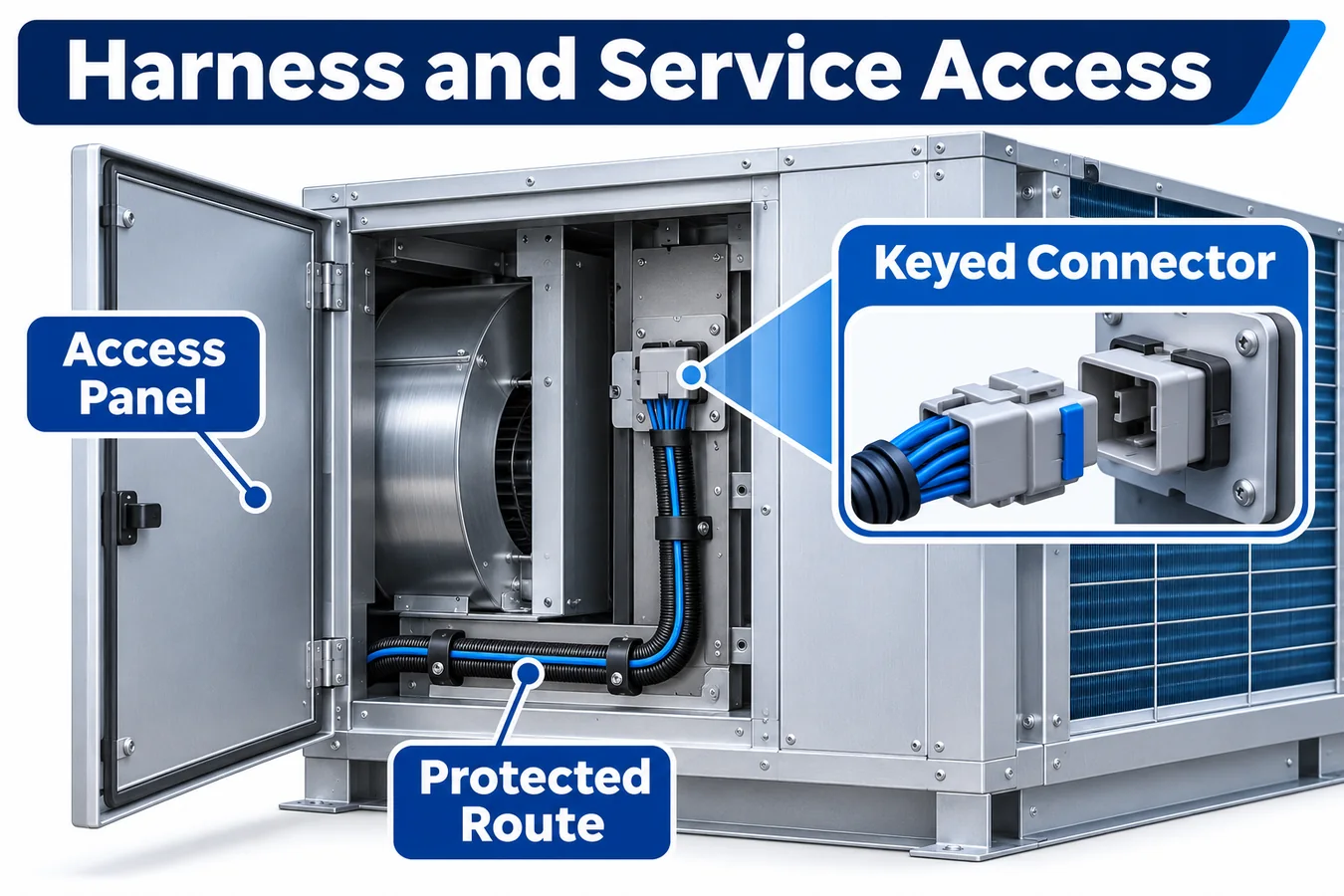
Review the harness with the doors installed and removed, the equipment oriented as shipped and as installed, and the relevant components partially withdrawn. Check that the sensing inlet and its mounting remain intact through a service action. Model the extra length needed for access without routing the service loop through a wet area, sharp edge or panel fastener path. Treat strain relief and the exit grommet as parts of the released construction.
Record cable length limits, connector keying, allowed harness revisions, retention method and any constraints on bundling or routing. Evaluate interactions with furnace and blower electrical activity at system level. Interface disturbances may be specific to a particular harness path or return reference. A scope trace at the controller end and the voltage at the detector can distinguish electrical interaction from gas exposure or a data interpretation error.
Make the approved configuration easy to restore. The service parts list should associate the detector revision, bracket, harness and controller compatibility information with the equipment model and orientation. Drawings and labels should identify which features distinguish the approved mount from mechanically plausible alternatives. Define what a service check can demonstrate after parts replacement, and retain lab validation as the evidence for transport across the assessed release cases.
9. Use a combination matrix to make release decisions
The following example assumes a cased coil with a separate dissipation controller and a gas furnace. It uses fictional variant labels. The programs and measurements referenced in the evidence column are examples of what the team would document for the specific equipment.
| Combination row | Geometry and interface assumption | Evidence required | Release decision |
|---|---|---|---|
| F1 and C1, upflow | Factory bracket, standard adapter, discrete interface | Transport from both header regions and physical response during existing heat and cooling calls | Baseline row after evidence review |
| F1 and C1, downflow | Alternate pan and detector bracket, same discrete board | Separate transport tests, harness service fit and confirmed blower behavior with the installed stack | Keep open pending orientation results |
| F2 and C1, upflow | Same coil geometry, communicating outdoor path | Shared transport evidence if airflow envelopes match, plus message authority and outdoor response trials | Assess shared evidence and close new interface tests |
| F2 and C2, horizontal right | Different coil pan, mounting arrangement and return conditions | Dedicated construction evidence and verification across representative blower states | Treat as a separate configuration |
Add drawing revisions, controller builds and evidence identifiers to the controlled matrix. “Pending” should identify the missing test or the unresolved ownership question. The matrix then serves as a review queue as well as a release record. It can also show why a service replacement or new furnace suffix cannot inherit approval from a superficially similar combination.
10. Validate the installed chain in layers
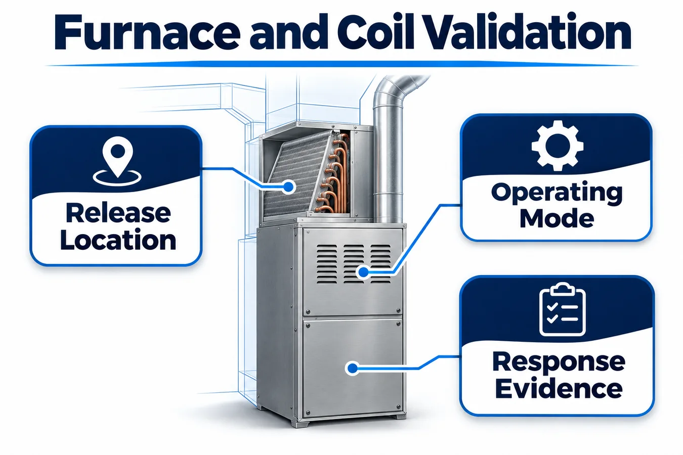
Begin with controlled fixture work to characterize access to the detector and separate inlet exposure from electronics behavior. Then use the representative coil and furnace assembly to challenge credible sources, orientations and blower states. Finally, run system tests with the released harness, power arrangement, controller revisions and participating equipment. Use a common timestamp basis for the relevant channels.
Log the tested geometry with photographs or setup drawings, including panel state, drain arrangement, reference instrument positions and accessory configuration. Capture controller acceptance and equipment responses with enough resolution to interpret the event ordering. When the acceptance criterion depends on air movement, document the measurement and location used to characterize it. The outcome is a record of the tested chain under identifiable conditions.
Plan how to treat a run with missing evidence. A trace with an actuator command and an absent physical measurement has a different evidentiary value from a trace that demonstrates both. A run with a shifted inlet reference may help identify a transport question but require repetition for acceptance. Declare those distinctions in the protocol so pressure to close the matrix cannot turn incomplete measurements into passing evidence.
11. Resolve evidence gaps before inheriting a row
Assume an engineering team wants to add a second furnace under a coil whose sensor mount is unchanged. The new furnace uses a different blower motor and a shorter adapter. In the original row, gas from the line connection reached the sensing inlet through the adapter side of the pan at low airflow. The proposed row changes two factors involved in that result. The smaller volume may change how the pocket fills, and the motor may reach a different operating point during a pending cooling call. Mark that release case for comparison even if the standard cabinet and sensor drawing remain the same.
Use a comparison test that can identify the difference. First characterize the relevant blower behavior on both stacks at the same defined system resistance. Then compare inlet exposure and system acceptance for the selected release path. If geometry or airflow differs, make the conditions explicit in the matrix and expand the affected trials as needed. If the traces agree within the protocol’s decision criteria, record which tested conditions support inheritance and which conditions the comparison leaves to other evidence.
Now consider a proposed field kit that makes assembly easier by putting a detachable connector near a service panel. The transport evidence may be applicable if routing and cabinet features remain equivalent. The electrical evidence has a separate question. The connector adds a point that can separate during service, and its contact or seal properties may differ from those of the approved harness. Review the connection at startup and during an active event. Identify the receiver behavior and the expected restoration check for that exact assembly. A single disposition for the whole kit can hide the fact that different evidence applies to its mechanical and electrical changes.
Close the row with an explicit acceptance owner. Provide that person the installation drawing, test evidence, exceptions and combinations still awaiting review. If the proposed row depends on an installer-selectable blower setup, specify how the released instructions identify it and how a production or commissioning record captures it. A matrix that assumes a setting without defining how it is established can appear complete while a representative installation uses another setting.
Keep a short cross-reference from the row to the change trigger for each inherited result. For the examples above, a motor revision could reopen the airflow and transition comparison, while a connector substitution could reopen the continuity and environmental work. The trace should also identify the legacy combinations that continue to use the original parts. This helps service engineering distinguish a permitted supersession from a new pairing that still needs review.
12. Manage evidence across manufacturing and field changes
Keep the validated combination identifier connected to the production record. Relevant controlled items can include coil revision, pan and adapter part numbers, detector and bracket identifiers, harness release, furnace and outdoor firmware and installation instructions. Use feature-based inspection for characteristics such as bracket orientation and connector retention when those characteristics govern the outcome. The check should reference the features used in validation.
Write explicit inheritance rules for changes. An enclosure repaint may need a materials or environmental review if exposure could affect the inlet. A different coil pan may require transport work. A blower firmware revision may require timing or airflow comparison even if the cabinet is identical. A replacement board with the same connectors may need review of its startup or request handling. State what evidence can be carried forward, what assumptions must be checked and who accepts the decision.
Capture service feedback in a form that can be mapped to the matrix. Orientation, equipment model and revision, field kit and harness version are often more valuable to the engineering review than a generic complaint about an alarm. If the report concerns an airflow issue during a particular operating phase, record that phase and the participating equipment state so the lab can reproduce it.
13. Evaluate the ZRT512E-R454B candidate

Winsen identifies the ZRT512E family for R454B and R32 applications. The ZRT512E-R454B is a candidate for an OEM feasibility review when the exact orderable configuration and supplied documentation fit the equipment project. Request the controlled drawing, interface specification, supported mounting conditions, environmental evidence and revision identifiers for the sample. Use those details to design the bracket and define the interface tests. Qualification rests on the installed combination and the evidence for the exact supplied configuration. Winsen ZRT512E family product page
14. Frequently asked questions
Can an upflow location be reused for downflow?
It can be considered for reuse when evidence covers the actual downflow construction. Compare pan, cabinet and adapter geometry, gravity relative to the inlet, pressure fields across the blower range, and access for assembly and service. Keep evidence separate where those conditions change the transport or installation mechanism.
Can the existing furnace fan input serve as the mitigation interface?
Assess the exact board and firmware under the installed wiring and all relevant furnace modes. Identify what the input requests and whether the furnace grants it while another operating function or fault is active. Confirm the physical airflow and required sequencing under the tested combination. A terminal name alone carries very little evidence about priority or response.
Can a service function test replace controlled release testing?
A service function test can establish defined portions of the electrical and equipment action chain under specified conditions. Controlled release testing addresses the route from the release to the sensing inlet and the resulting detection behavior. A release package should identify which portions each method covers and map them to separate evidence.
How much evidence can two cabinet sizes share?
Build the equivalence case from the actual transport mechanisms. Compare pan and slab geometry, openings, relative detector position, airflow and relevant tolerances. If the larger cabinet adds a low pocket or changes flow distribution, preserve a separate test for that case. Record the logic behind each inherited result so a later design change can be evaluated against it.
15. Request an OEM integration review
Send Winsen the approved and proposed furnace–coil–outdoor combinations, section drawings showing orientation and airflow, credible release regions, detector power and interface requirements, and the draft test matrix. Include the expected handling of existing calls and the evidence your team needs for the assessed equipment. Ask for the controlled ZRT512E-R454B configuration documentation and representative samples for the intended interface.
Use the review to close a specific engineering decision. Agree which prototype assembly and detector revisions will be paired, which release zones and blower transitions the lab will challenge, and which boards will provide timestamped evidence of the physical response. Keep open combinations visible in the matrix until the remaining evidence is complete. Winsen OEM contact
Review the ZRT512E product listing Và submit the equipment details for an OEM integration review.
