
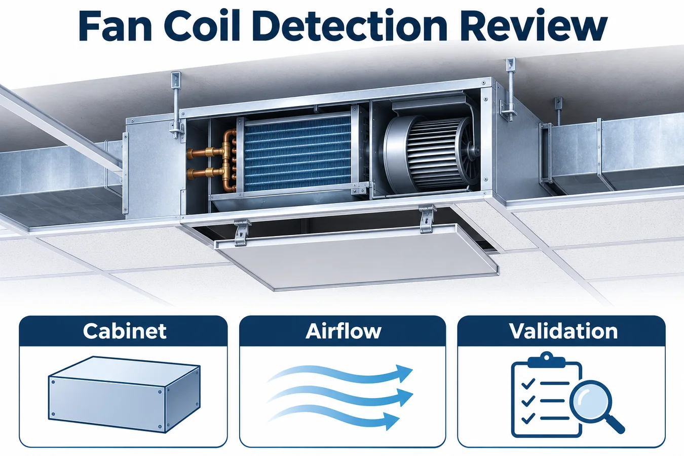
MỘT Cuộn dây quạt cảm biến R454B dự án bắt đầu với thiết bị sẽ được lắp đặt thực sự. Mỗi tủ được giấu nông, một khoang thông gió trở lại, một hộp lọc tùy chọn và một lỗ mở trên trần có thể ảnh hưởng đến việc phát hiện hoặc bảo trì. Nhóm thiết bị cần có mối quan hệ xác định giữa việc giải phóng chất làm lạnh đáng tin cậy, khí đến máy dò, đầu vào bộ điều khiển hợp lệ và phản hồi của thiết bị vật lý.
Hướng dẫn này giả định một dàn lạnh có ống dẫn minh họa có cuộn dây, quạt gió có động cơ, khay ngưng tụ và thiết bị ngoài trời được kết nối. Ví dụ mô tả các quyết định kỹ thuật và bằng chứng để yêu cầu. Các yêu cầu chính xác về thiết bị, hướng dẫn cài đặt và chương trình chứng nhận sẽ xác định chức năng phát hiện và giảm thiểu được phát hành. UL Solutions mô tả một hệ thống phát hiện chất làm lạnh tích hợp giống như cảm biến cố định kết hợp với giảm thiểu tự động và giải thích đánh giá của nó trong thiết bị. Hướng dẫn RDS tích hợp của Giải pháp UL
Xác định cấu hình cuộn dây quạt nào mà bằng chứng đề cập
Tạo sổ cái cấu hình trước khi so sánh các máy dò. Ghi lại kích thước tủ, cấu trúc cuộn dây, sửa đổi chảo, cụm quạt gió, cách bố trí đầu vào và đầu ra, bộ điều khiển, nhận dạng chất làm lạnh và hướng lắp đặt đã được phê duyệt. Thêm hộp trả lại, máy bơm, máy sưởi và bộ chuyển đổi hiện trường tùy chọn khi chúng thay đổi đường dẫn khí, phụ thuộc điện hoặc tuyến dịch vụ. Chỉ định mỗi cách sắp xếp có thể xây dựng được một mã định danh ổn định được kết nối với danh mục vật liệu.
Dòng ống dẫn âm có thể sử dụng một bệ điện tử trên nhiều độ sâu của tủ. Bảng mạch chung đó có thể đơn giản hóa việc phát triển giao diện trong khi các biến thể cơ học vẫn yêu cầu xem xét vận chuyển riêng biệt. Một ngăn kết nối bên cạnh cũng có thể di chuyển giữa các kích cỡ. Xác định các đặc điểm biện minh cho bằng chứng được chia sẻ và những khác biệt đòi hỏi phải làm việc nhiều hơn. Sổ cái phải thể hiện rõ những sắp xếp bị bỏ qua trước khi mô hình tiếp thị mở rộng.
Separate appliance options from surrounding installation conditions. The OEM may define a permitted duct resistance envelope while the actual duct layout is supplied by others. State the boundary conditions represented in the tests, which instructions establish them and how their applicability is checked. Include the maximum relevant refrigerant inventory for the approved equipment combinations in the program’s controlled requirements, without turning an illustrative article into a charge prescription.
Cung cấp cho mỗi hàng một chủ sở hữu và trạng thái bằng chứng. Một hàng mở sẽ chỉ ra một bản dùng thử bị thiếu, ý nghĩa giao diện chưa được giải quyết hoặc một bản vẽ đang chờ phát hành. Sau đó, người đánh giá có thể quyết định liệu lô hàng được đề xuất có được bảo hiểm hay không, thay vì suy ra sự chấp thuận từ tên nội các chung.
Lập bản đồ tủ giấu và đường dẫn khí được kết nối
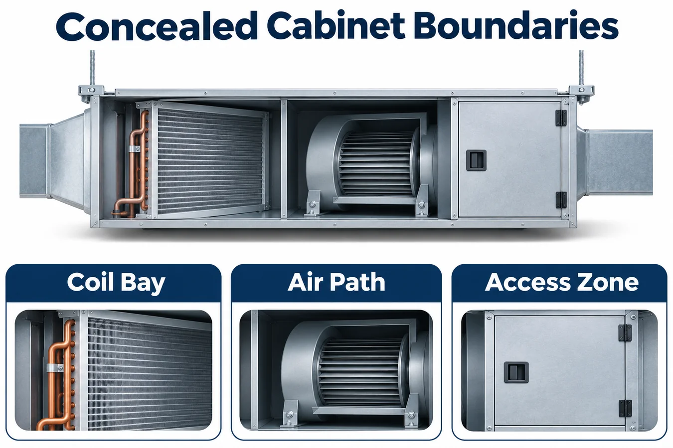
Vẽ các mặt cắt qua khoang cuộn dây, khoang quạt, khu vực điện và các kết nối. Hiển thị hướng trọng lực được cài đặt độc lập với hướng luồng khí thông thường. Bao gồm các cạnh chảo, các mối nối cách nhiệt, các lỗ ống, các đoạn dây nịt, các nắp có thể tháo rời và các kết nối cống. Đối với hệ thống lắp đặt ẩn, hãy vẽ các giao diện cung cấp và trả lại đã được phê duyệt cũng như đường bao truy cập xung quanh tủ.
Use the drawing to ask where gas can travel with the fan idle and how operation changes that route. An insulation strip can partition a pocket even when the exterior cabinet is continuous. A negative pressure compartment may draw air through a seam, while a neighboring positive pressure region releases air through another opening. The specific construction and operating condition establish which mechanism matters.
Distinguish the equipment air path from the surrounding ceiling void. If the design relies on containment or exchange across a boundary, identify the controlled construction that supports that assumption. A removable service cover may have different leakage after repeated access. A field return box can introduce a new seam or pocket. Bring those features into the evidence plan wherever they affect the claimed detection function.
Keep candidate sensing locations as engineering hypotheses until representative trials establish coverage. An accessible surface can be attractive for service and still have weak exposure to a release behind a pan divider. A position with good inlet exposure must also remain compatible with moisture, temperature and mounting requirements.
Build release cases from the refrigerant construction
Assign source identifiers to relevant coil headers, distributor regions, feeder joints, return bends and connection areas within the assessed boundary. Describe each source’s relationship to cabinet partitions and the airflow field. Group cases only when their transport mechanism is credibly equivalent. Geometric proximity alone may conceal a dividing flange or a route into another compartment.
For an illustrative narrow cabinet, assume the coil connection area lies beside a pan lip. With the blower idle, a release from the connection region first enters the side volume. During blower operation, that volume exchanges with a faster moving stream near the slab edge. The test plan should address the idle pocket and the operating transport path, including the transition between them if its mechanism differs from either steady case.
Ghi lại lý do đằng sau điểm phát hành đại diện. Một ống cố định hướng thẳng vào máy dò có thể tạo ra một đường dẫn mà mối nối thực tế không cung cấp. Tham chiếu hình dạng nguồn đã cài đặt, xâm nhập tài liệu cố định và giữ ổn định các vị trí đo tham chiếu. Khi quy trình sử dụng một thỏa thuận thay thế cho công việc sơ bộ, hãy xác định những kết luận nào vẫn cần thử nghiệm thiết bị đại diện.
Theo dõi mọi trường hợp phát hành trở lại bản vẽ. Khi khớp di chuyển, bản sửa đổi cuộn dây sẽ thêm nắp hoặc bộ kết nối thay đổi vỏ của nó, nhóm có thể xác định các trường hợp bị ảnh hưởng. Bản đồ phát hành trở thành một công cụ đánh giá thay đổi thực tế hơn là một bức ảnh được lưu trữ bên cạnh báo cáo thử nghiệm.
Bao gồm các trạng thái quạt và chuyển tiếp một cách rõ ràng
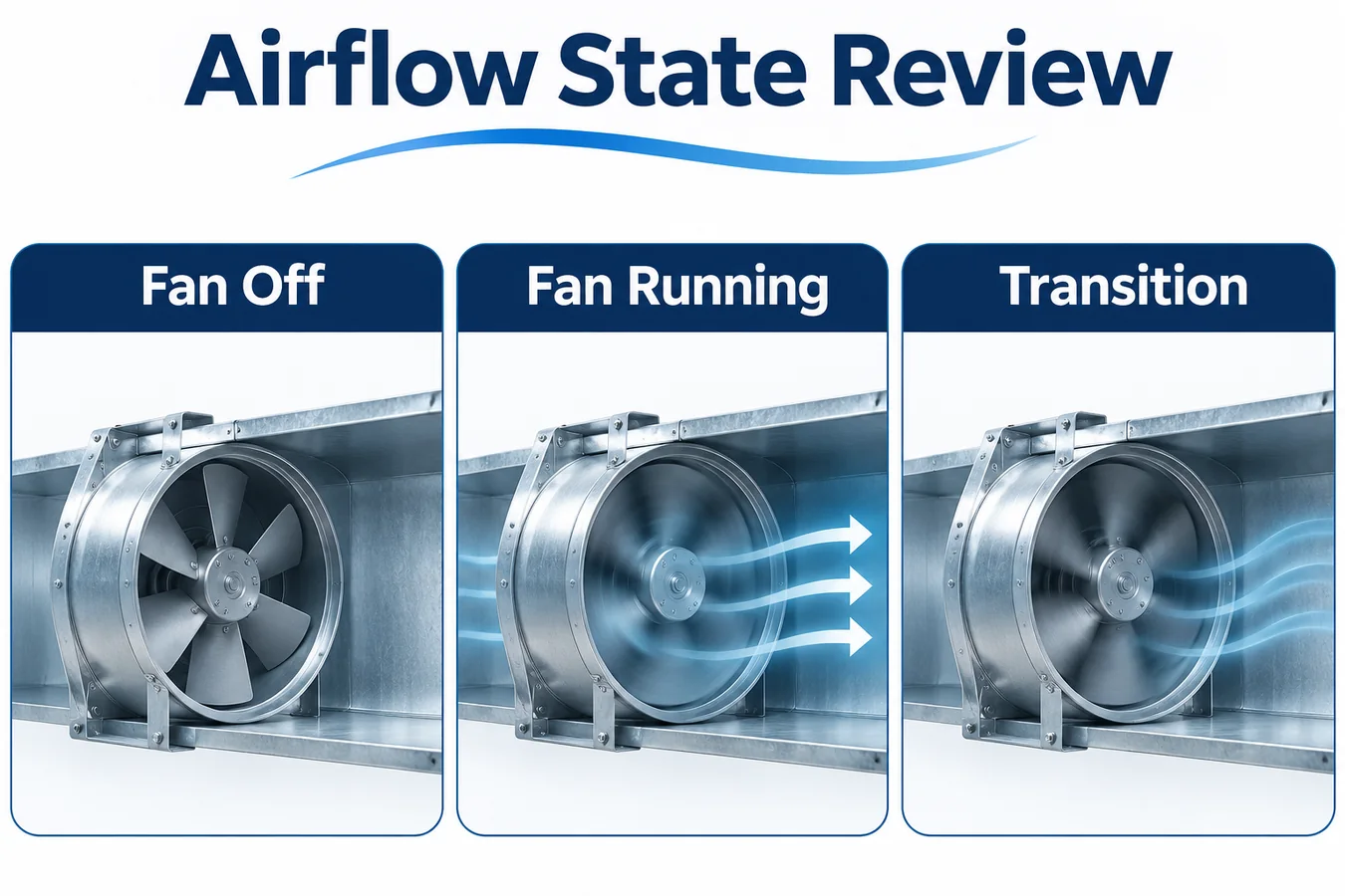
Build the operating map around actual blower behavior. Include relevant idle, low flow, normal demand, shutdown and mitigation states, as well as transitions that change the transport route. Record the requested mode and the observed equipment condition separately. A command can be present while the motor ramps or a receiving board delays action.
Select trials across the approved external resistance range using the mechanism being challenged. A low flow condition may create a long residence time in a cabinet pocket. Higher flow may dilute inlet exposure or redirect gas. A fan start can clear an idle collection zone before another sensing region receives the release. The useful comparison connects the observed inlet exposure with the operating condition.
In a variable speed platform, log the actual control mode and any automatic adaptation that changes airflow. If an accessory controller or building command can select a mode, establish how the mitigation request interacts with that authority. A test at one nominal setting does not establish priority across all available modes.
Tránh coi phản hồi của quạt gió là bằng chứng đầy đủ về sự vận chuyển khí. Động cơ có thể đạt được trạng thái yêu cầu trong khi hình dạng của tủ vẫn định tuyến đường thoát ra khỏi cửa nạp. Bằng chứng về vận chuyển và bằng chứng về cơ cấu chấp hành gặp nhau trong thử nghiệm hệ thống được lắp đặt, với mỗi phép đo giải thích một phần khác nhau của chuỗi.
Cùng nhau xem xét khả năng tiếp xúc với nước ngưng và khả năng tiếp cận dịch vụ
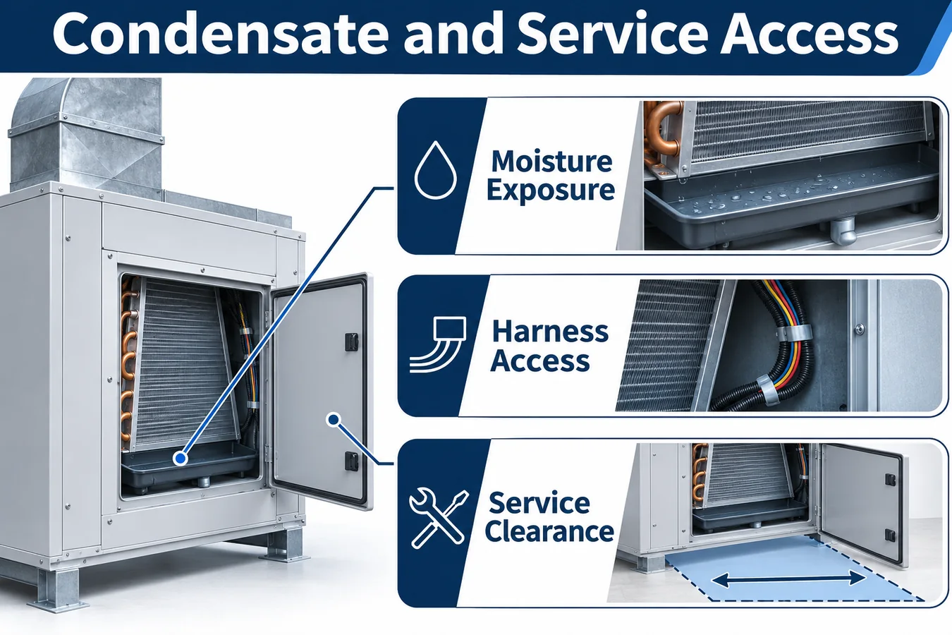
Xem lại hoạt động ướt với cùng các bộ phận của tủ và chảo dành cho sản xuất. Xác định các tuyến ngưng tụ thông thường, các cơ chế bắn tung tóe hoặc mang theo có liên quan đến thiết bị và mức phơi nhiễm tại máy dò và đầu nối ứng cử viên. So sánh các điều kiện đó với tài liệu về môi trường của cấu hình máy dò chính xác. Bao gồm việc khởi động sau tình trạng ẩm ướt hoặc không hoạt động kéo dài mà chương trình thiết bị xác định là có liên quan.
Ghi lại hướng giá đỡ và đầu vào bằng cách sử dụng các mốc đo lường được kiểm soát. Hướng dẫn chung để giữ cho cảm biến khô ráo không xác định cách lắp ráp. Ghi lại kết cấu lắp đặt được phép, dung sai và lối vào để kiểm tra. Đánh giá bất kỳ lớp phủ hoặc tấm chắn nào như một phần của đường dẫn cảm biến vì tính năng được giới thiệu để bảo vệ độ ẩm cũng có thể làm thay đổi quá trình trao đổi khí.
Đối với thiết bị được giấu kín, hãy mô phỏng dịch vụ thông qua lỗ truy cập dự kiến. Xác định xem kỹ thuật viên có thể xác định bộ phận, tháo đầu nối và khôi phục giá đỡ mà không cần tháo ống dẫn không liên quan hoặc thay đổi hướng đầu vào hay không. Kiểm tra hoạt động của tủ theo hướng được lắp đặt và có vật cản thông thường.
If the unit needs a particular access envelope, connect the mechanical drawing to the installation documentation. Serviceability affects whether the validated construction can be restored after replacement. The review should identify observable features a technician can compare with the released illustration, including connector retention and harness clearance when panels close.
Assign control authority across the indoor and outdoor equipment
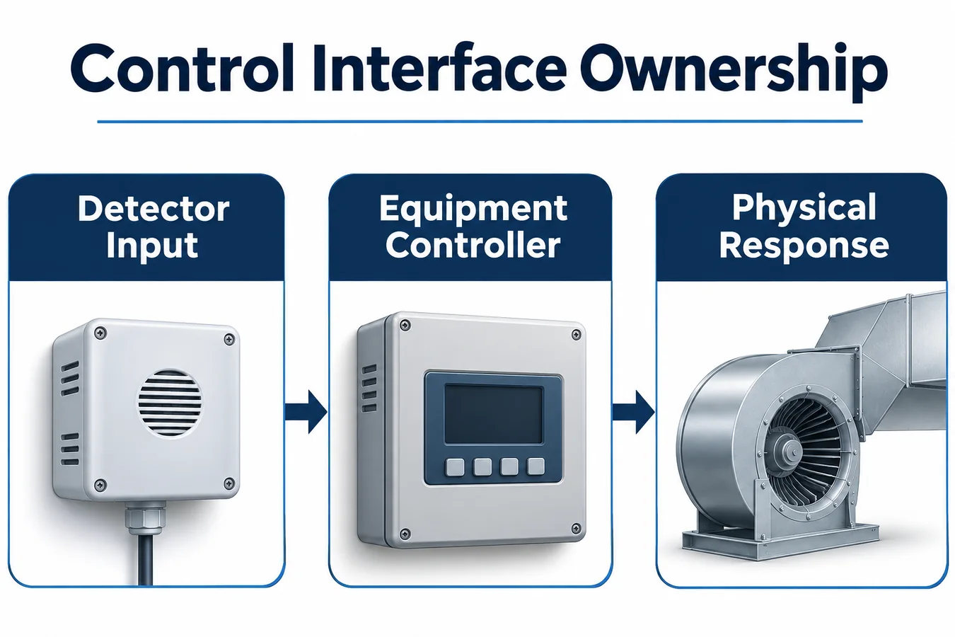
Xác định ai xác thực đầu vào của trình phát hiện, ai quyết định trạng thái giảm thiểu và ai sở hữu từng đầu ra vật lý. Bảng trong nhà có thể ra lệnh cho quạt gió trong khi bộ điều khiển ngoài trời có quyền sử dụng máy nén. Giao diện tòa nhà có thể mang chỉ dẫn về nhu cầu hoặc trạng thái mà không có thẩm quyền phát hành một sự kiện được giữ lại. Viết những khác biệt này vào đặc tả giao diện.
Đối với mọi kết nối, hãy nêu ý nghĩa được xác nhận, điều kiện hợp lệ, hành vi khởi động và chính sách đầu vào không khả dụng. Nếu một báo cáo kỹ thuật số chứa đựng sự tập trung và trạng thái, hãy thiết lập những trường nào khiến quan sát đủ điều kiện. Nếu sử dụng một cấp độ riêng biệt, hãy ghi lại các giả định về điện và công suất cần thiết để diễn giải từng cấp độ. Xem lại bo mạch và chương trình cơ sở chính xác ở đầu nhận.
Illustrate one interrupted sequence. Assume the indoor controller accepts an event, sends the approved request to the outdoor board and then restarts. Determine what the outdoor board observes while the indoor software initializes, what information is retained and which observations must be acquired again. Use measurements at the actual equipment interfaces to establish the physical behavior.
A building command or ordinary thermostat request can arrive during that sequence. The released output arbitration must define its effect while restrictions are active. Keep a single accountable policy for the outputs so a comfort control task cannot overwrite a mitigation command on its next update.
Distinguish commands, acknowledgments and physical proof
Draw the detection and response timeline using identifiable landmarks. Include gas arrival near the inlet, eligible detector output, controller acceptance, output request, receiving-board response and the physical outcome used by the equipment program. The intervals help the lab distinguish transport delay from signal handling or actuator behavior.
An acknowledgment establishes the meaning defined by its interface contract. It may confirm that a message arrived without proving the requested airflow. Select evidence that supports the actual acceptance criterion. Where direct measurement is required in qualification, record the instrument, location and operating condition used to characterize the response.
Define how existing operation affects proof. If the fan is already running when an event arrives, determine whether its current status qualifies for the required mitigation operating condition. A status sample captured before the mode change can require freshness or mode information before the supervisor uses it. The decision should be explicit in the test protocol.
Include a trial where the command is accepted but the intended physical response is unavailable. Observe the equipment’s defined restricted behavior and retained state. A trace containing a command alone cannot close a requirement about an actuator outcome. Give partial evidence its own disposition so incomplete measurements remain visible.
Use a configuration and evidence matrix
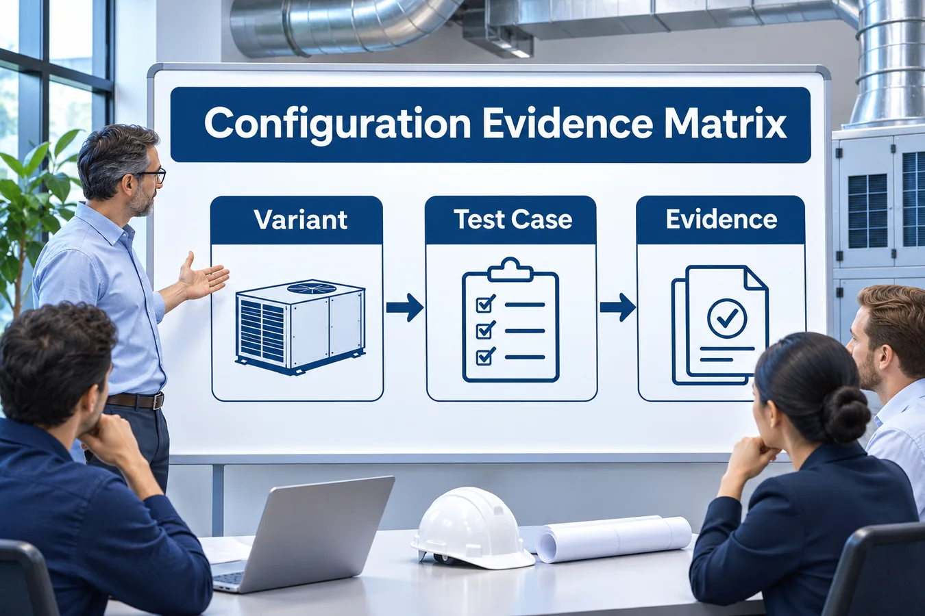
The following example uses fictional variants of a concealed duct fan coil. It illustrates how a team can organize decisions while the actual acceptance criteria stay in the controlled equipment requirements.
| Variant | Changed feature | Engineering question | Evidence to close |
|---|---|---|---|
| Shallow cabinet baseline | Standard pan and direct return | Do selected sources reach the inlet across the offered fan modes? | Representative transport and response trials |
| Return box option | Added enclosure and seam | Does the option introduce a collection or exchange route? | Geometry comparison and affected release cases |
| Pump option | Different service parts and power dependency | Can installation and replacement preserve the validated assembly? | Wet exposure review, power analysis and access trial |
| Alternate blower | Different motor and control program | Does the transition or available airflow change? | Fan characterization and repeated affected cases |
| Remote controls option | Changed request and status path | Is output authority maintained through link interruption? | Interface and restart evidence |
Give each row drawing, firmware and evidence identifiers. Capture why an inherited result applies and which physical or electrical characteristic would invalidate that inheritance. A simple “same as baseline” entry leaves the next engineer without a basis for judging a component change.
Use the matrix to select meaningful trials. It can reduce repetition when evidence supports equivalence while preserving dedicated trials for different mechanisms. The reviewer should be able to see which rows are released, which remain open and what concrete work is needed to change their status.
Plan installed testing in layers
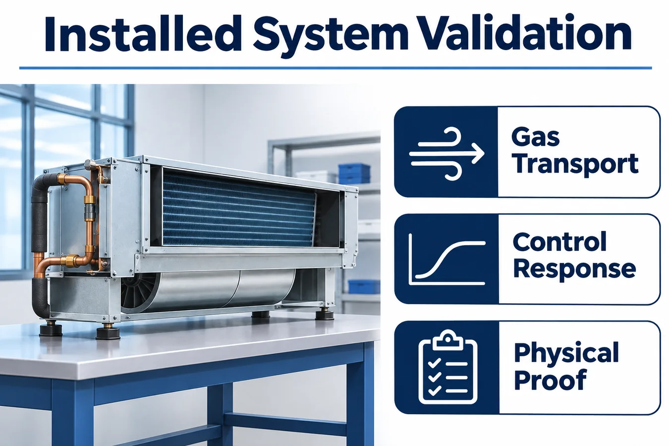
Begin with controlled fixture work to understand inlet exposure and detector behavior. Move to representative cabinets to evaluate release paths, then exercise the assembled equipment with its actual controller and actuators. Maintain common identifiers across these stages so an observation in a fixture is not mistaken for an installed result.
Record cabinet and pan revisions, panel state, filter and return arrangement, blower configuration, interface revision and detector sample identity. Include photographs that locate the reference instruments and source fixture against cabinet datums. These details allow the lab to reproduce a disputed trace or identify which later variant needs additional work.
Set rules for missing or unusable data before trials begin. A shifted reference instrument, an interrupted controller log or an unrecorded fan mode can limit what a run establishes. Keep the trace for diagnosis, assign its evidence status and repeat the affected acceptance work where needed. This protects the matrix from closing a requirement that was never observed.
After the installed sequence is established, challenge power and signal dependencies. Test the relevant detector, decision-board and actuator-board restart combinations, including the case where only one board loses power. Inspect the actual outputs during boot and the point where current status becomes eligible again. The physical chain includes the intervals before application software resumes.
Work through a concealed unit example
Assume the baseline cabinet is released with a particular pan, blower program and return arrangement. A product change adds a return box to simplify installation. The enclosure attaches to an existing flange and leaves the sensor assembly untouched. The change request claims the detector and controller tests can be inherited.
The reviewer first compares the transport drawing. The new box introduces a volume beside the connection compartment and changes a seam that exchanged with the surrounding space. The affected source cases are identified from the release map. The team chooses comparison trials with the fan idle, at a relevant low flow condition and during the transition that changes exchange at the seam.
Next, the reviewer compares the electrical arrangement. If detector power, harness and controller remain equivalent, existing interface evidence may remain applicable, subject to the documented review. If the option also moves the control enclosure to improve access, harness routing and disturbance exposure enter the scope even though the schematic appears unchanged.
The final disposition separates evidence by mechanism. Transport trials close the added volume and seam questions. A service mock-up confirms that the access opening permits restoration of the intended assembly. Applicable electrical evidence is referenced with its inheritance basis. The row is released only after each identified question has a disposition and the drawings describe the tested construction.
Compare service access with gas exposure on the installed cabinet
Consider a shallow cabinet offered with either a full-width return opening or a side-entry return box. Both versions use the same coil and control board. The full-width version has an access panel under the coil bay, while the side-entry version has an additional divider and a smaller opening for reaching the sensor. A candidate position behind that opening makes replacement straightforward, but the divider may change how refrigerant from a connection bay reaches the sensing opening. The drawing and airflow study should account for both the divider and the production service panel.
Start the comparison by writing down what each design is intended to improve. A detector near the access opening can be easier to identify and replace. A detector closer to the coil bay can shorten the expected transport path for some release sources. The harness on either side may need a different retention or strain relief arrangement. Ask the mechanical team to confirm bracket and connector clearances on the installed unit, including the ceiling access envelope represented in the instructions.
Then use the same release and controller observations to evaluate both options. Compare fan-off, fan-running and relevant transition cases selected by the program. Record detector response and the resulting equipment actions, with the access cover and return box in the released condition. A test performed with a service panel removed may be useful for troubleshooting. Its airflow boundary should be recorded clearly before its evidence is used to support a closed-cabinet construction.
A successful service trial should include identifying the part, reaching the fasteners, reinstalling the approved harness route and confirming that the sensing opening is exposed after closure. Record what the technician could see and what the instruction had to specify. If the return box is installed in the field, link the approved combination to the equipment identification and the box instructions. The release package should make the approved configuration easy to recognize before it is enclosed above a ceiling.
Keep manufacturing and service records connected
Translate the validated assembly into production features that can be inspected. Record the detector and bracket revision, harness identity, connector retention and panel or seal features involved in the evidence. Use a fixture or visual check suited to the characteristic. A part-presence check alone may miss a reversed mount or a trapped service loop.
Maintain exact compatibility information for service. The replacement record should connect the unit model and serial range with the detector configuration, bracket, harness and required restoration checks. If a supersession changes initialization or status behavior, review the receiving firmware and update the service path accordingly. A connector fit establishes only a mechanical fact.
Feed field observations back into the configuration ledger. Useful reports identify the actual unit, option kit, orientation, operating phase and part revisions. A description tied to those details can lead to a repeatable lab case. A generic “alarm problem” report leaves the engineering team guessing which combination and mechanism to investigate.
Define change triggers for renewed review. Pan geometry, insulation, blower programming, return accessories, controller firmware and service parts can affect different portions of the evidence. Identify the affected matrix rows and make the inheritance decision explicit, including the owner who accepts it.
Evaluate the ZRT512E configuration as a candidate

Winsen lists the ZRT512E family for R454B and R32 applications. Treat the exact ZRT512E-R454B configuration as a candidate for the fan coil program. Request the controlled mechanical drawing, gas configuration, interface specification, environmental evidence and revision identification associated with the intended orderable part. Qualification depends on the supplied configuration and its installed integration. Winsen ZRT512E family information
Use the sample review to connect supplier documentation with equipment decisions. Compare the mounting and exposure assumptions with the cabinet concept, then agree the interface behavior needed during startup and interruption. Preserve sample identifiers in the test report so later procurement and production work can trace the evidence. Review the local product information with the controlled supplier package. ZRT512E product candidate
Câu hỏi thường gặp
Can one concealed unit size represent the whole family?
It can represent the conditions for which the equivalence case is supported. Compare transport geometry, source locations, pan and partition details, fan behavior and interface architecture. Keep separate evidence where a difference changes the mechanism being assessed. Record the boundary of every inheritance decision.
Does a function test prove the mounting location?
A function test can demonstrate defined electrical and actuator behavior. The path from a credible release to the sensing inlet requires transport evidence under representative cabinet and operating conditions. Identify the portion of the chain each method establishes and keep both in the release package.
Should the most accessible mounting surface be selected?
Accessibility belongs in the decision alongside exposure, environment and assembly consistency. Evaluate candidate locations against the release cases and the exact detector’s mounting documentation. A service mock-up then checks whether the validated construction can be identified and restored through the intended access.
Can a building controller release the event?
The equipment requirements define authorization and recovery. Document what the building interface is permitted to request, which component decides eligibility and what happens when the communication path is unavailable. Verify that ordinary commands do not change the defined restrictions during an active or retained event.
Request an OEM fan coil integration review
Prepare cabinet sections, offered orientations, pan and return options, refrigerant source regions, fan operating envelopes and the proposed control contract. Add the configuration matrix and identify which evidence your lab plans to obtain. Ask for the exact candidate documentation and representative samples that match the intended supply and interface.
Use the review to close specific questions about detector exposure, installed environment, interface validity and sample identity. Agree which prototype revisions the first trials will use and how the evidence will connect to the release ledger. Share the equipment context and request an application discussion through the local OEM contact. Contact the refrigerant sensor team
