
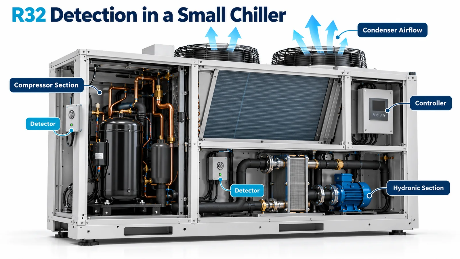
A compact air-cooled chiller concentrates several engineering disciplines inside one enclosure: a refrigerant circuit, high-power compressor, condenser airflow, hydronic piping, pumps, electronics, weather protection and service access. When the refrigerant is R32, a detector must work within this changing mechanical environment and still provide the controller with timely, trustworthy information.
Effective R32 leak detection in a small chiller не достигается размещением одного модуля в самой нижней видимой точке. В проекте необходимо связать надежные источники выбросов с транспортировкой газа в отсеке, воздействием детектора, приоритетом контроллера, обратной связью от исполнительного механизма и проверкой производства. Ветер, регулировка вентиляторов, работа компрессора, утечки воды и наличие нескольких контуров — все это может изменить эту цепочку.
В этой статье OEM-инженерам предлагается системный метод. Он не предписывает универсальный порог срабатывания сигнализации, количество детекторов или последовательность управления. Эти решения должны соответствовать применимым требованиям к оборудованию, выпущенной конструкции безопасности, действующей контролируемой документации на продукцию и программе сертификации для целевого рынка.
1. Define the Safety Function and Chiller Boundary
Begin by defining what equipment is included. A “small chiller” may be a packaged outdoor unit, a modular bank, a split hydronic product, a reversible heat pump chiller or an indoor machine with remote heat rejection. The boundary determines which releases the integral detection function covers and which controller can act.
Record the refrigerant, charge per circuit, number of circuits, compressor types, heat exchangers, service features, factory and field joints, hydronic options, enclosure versions, fan options, installation environment and applicable controlled requirements. Identify occupied or machinery-space interfaces, even for outdoor equipment. A leaking circuit can communicate with a building through pipe penetrations, ventilation openings or an attached module.
Define the intended output of the safety function: detection, compressor isolation, fan state, pump state, valve action, annunciation, communication to a building system and recovery. Then allocate responsibility across detector, chiller controller, power components and actuators. The sensor provides information; the installed chiller system must turn that information into the verified physical result.
2. Map Every Refrigerant Circuit and Release Source
Наложите схему хладагента на трехмерный корпус. Промаркируйте компрессоры, нагнетательные и всасывающие соединения, теплообменники, аккумуляторы, ресиверы, если они используются, реверсивные клапаны, расширительные устройства, распределители, датчики давления, разгрузочные пути, сервисные клапаны, заправочные патрубки и заводские паяные соединения. Для нескольких цепей используйте разные цвета и сохраняйте идентичность цепей с помощью карты ввода-вывода контроллера.
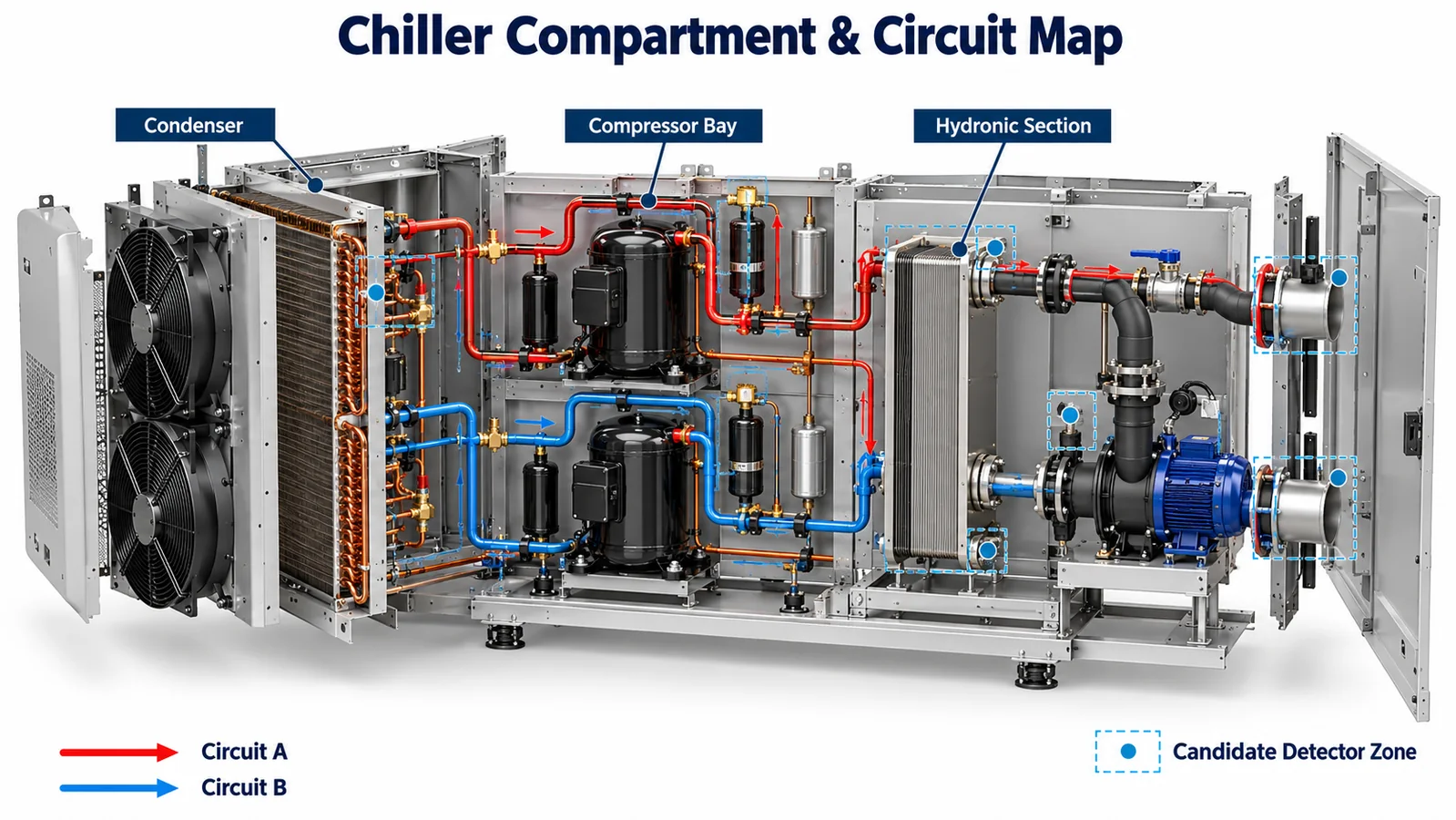
Group credible sources by compartment and release behavior. A compressor-terminal or shell connection may sit in a warm, ventilated bay. A brazed joint near a plate heat exchanger may sit beside hydronic insulation and water fittings. A condenser return bend may be exposed directly to wind and fan flow. Release momentum, phase and impingement can create different early gas paths even when total leak rate is similar.
The map should drive analysis and validation points. It should also drive change control: if tubing routing, a valve supplier or a service-port position changes, the team can see which tests and detector-coverage arguments need review. Avoid selecting only convenient laboratory release points that favor the proposed sensor.
3. Относитесь к переборкам как к гипотезам, а не как к идеальным барьерам.
Небольшие чиллеры обычно разделяют компрессорную, конденсаторную, гидравлическую и электрическую зоны. Переборки из листового металла уменьшают поток воздуха, воду и электрическое воздействие, но их кабельные вводы, отверстия для труб, сливные отверстия и швы могут пропускать газ. Детектор в одном отсеке не закрывает автоматически соседний.
Для каждой границы задокументируйте отверстия и разницу давления в разных рабочих состояниях. Для выявления замены используйте дым, индикаторный газ, измерения давления или тесты воздушного потока. Обратите внимание на нижние края перегородок и перекрытых каналов. Хладагент может попасть по кабельному лотку или трубке в место, не заметное при осмотре с открытой панели.
If the safety concept relies on a partition isolating an outdoor-dispersed release, validate that construction at tolerance extremes. If it relies on gas crossing a partition to reach one detector, validate the minimum exchange path and ensure production sealant or grommet changes cannot remove it. Either assumption needs evidence.
Electrical sections deserve special consideration. Protect electronics from water and refrigerant exposure, but do not route gas intentionally toward potential ignition sources merely because a controller is convenient to wire. The sensing and electrical architecture should be resolved together.
4. Evaluate Natural Wind and Condenser-Fan States
Outdoor airflow is rarely repeatable. With condenser fans off, wind can enter louvers, recirculate through a fan opening or pressurize one side of the enclosure. With one staged fan on, flow may bypass the candidate detector. At full speed, strong dilution may reduce local concentration while moving gas quickly out of the enclosure.
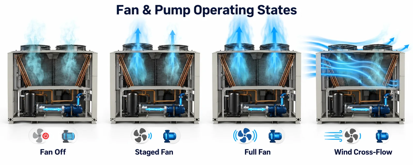
Analyze no-wind and representative wind directions, not just a nominal prevailing direction. Include fan off, minimum/staged operation, full operation, fan cycling and relevant fan-fault conditions. If variable-speed fans respond to ambient or load, identify the speed that produces the limiting transport to each detector.
Wind-tunnel testing is not always necessary in early development, but the final validation method must represent the installation envelope claimed by the product. A laboratory with panels removed and no external flow may demonstrate sensor electronics while saying little about outdoor system response.
Use CFD or flow visualization to understand mechanisms and select tests. Treat model results as engineering evidence with assumptions, not as a substitute for production-intent release trials. Small gaps and fan wakes are difficult to represent accurately without validation.
5. Include Pump and Hydronic Operating States
The hydronic system changes temperature, vibration, condensation and cabinet airflow. A running pump can warm a compartment and introduce vibration. Cold water or glycol can create condensation on pipes and panels. A pump or water leak can wet the detector, connector or harness. Insulation can shift during service and block a gas path.
Consider pump on/off, freeze-protection circulation, standby, flow loss, drain-down and water-leak conditions relevant to the product. If a valid refrigerant alarm occurs, decide whether the pump continues, stops or follows another sequence based on the released system analysis. The correct action is application-specific; it should not be copied from compressor logic without considering freeze, heat-transfer and dispersion effects.
Hydronic pressure relief or air vents can create local airflow and moisture. Glycol or treatment chemicals may be credible interferents or material exposures. Obtain the detector supplier’s restrictions and evaluate the actual fluids and cleaners allowed by the chiller manual.
Местоположение датчика должно оставаться репрезентативным при установленной изоляции и после обычного обслуживания. Детектор, спрятанный между холодной изоляцией и стеной, может обнаружить конденсат и застойный карман, а не газовое поле отсека, используемое в расчетах.
6. Защитите детектор от дождя, конденсата и утечек воды.
Наружные чиллеры нуждаются в дренаже. Дождь может попасть в жалюзи, ветер может сбить капли горизонтально, вода для промывки конденсатора может попасть в неожиданные места, а гидравлические соединения могут протечь. Защита от воды не должна охватывать датчик настолько плотно, чтобы реакция газа задерживалась или перенаправлялась.
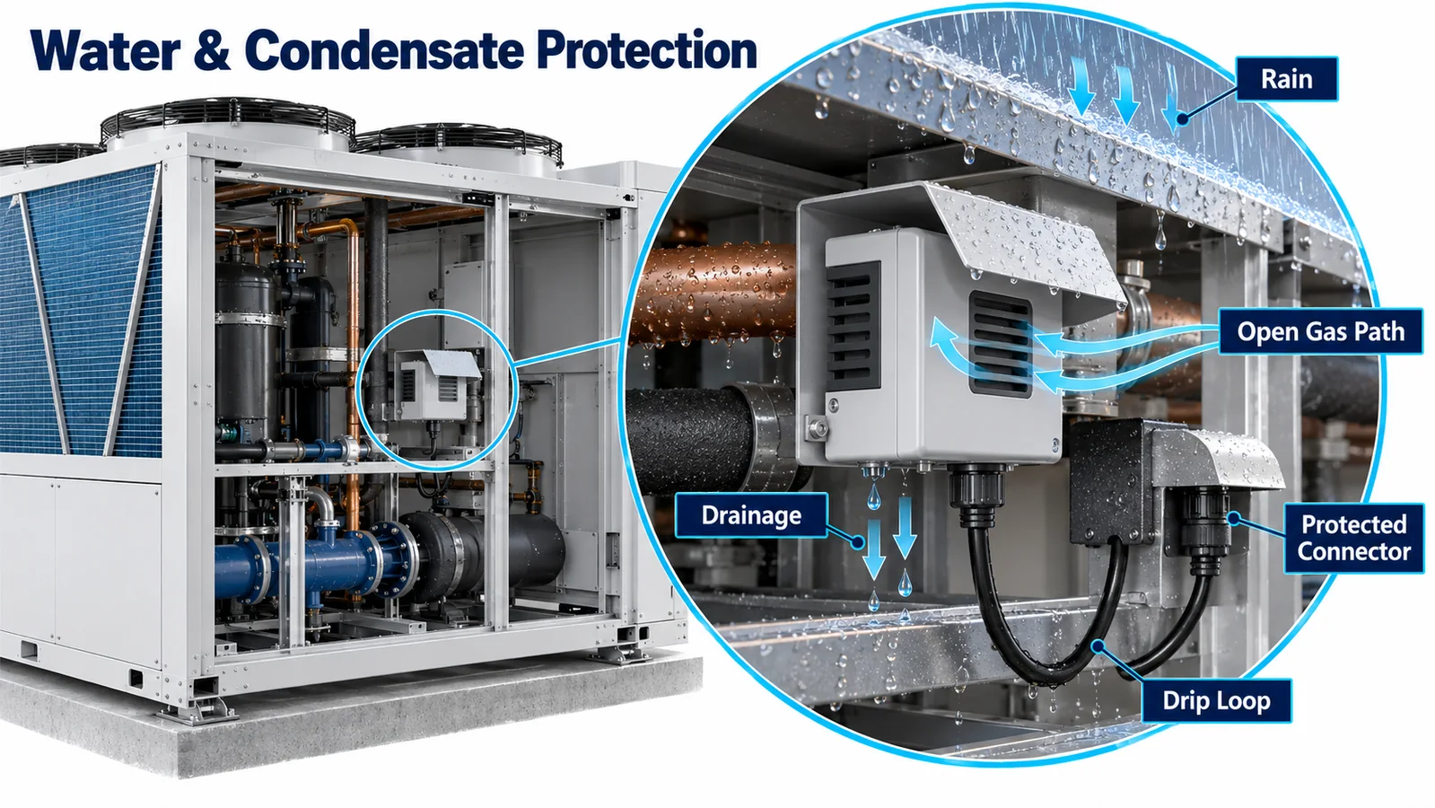
Choose a location outside direct spray and drain paths. Use drip loops and connector orientation to keep water from following the harness. Provide a roof, baffle or splash shield with an open diffusion path and a bottom drain. Avoid upward-facing cups, foam pockets or fine meshes that retain water and dust.
Test the installed assembly under rain, spray, condensation and freeze/thaw conditions appropriate to the product. Follow environmental exposure with detector diagnostics and gas-response checks. A dry visual inspection does not show whether residue or corrosion changed response.
Do not assume a module-level environmental rating applies to a modified assembly. A new cover, membrane, potting process, connector or bracket can change water behavior and gas transport. Controlled detector documents and chiller-level tests must cover the production configuration.
7. Decide Detector Count From Coverage, Not Circuit Count Alone
One detector per circuit can be logical when circuits occupy distinct compartments, but circuit count is not a universal rule. One detector may cover several circuits if releases share a proven gas path. One circuit may require multiple detectors if bulkheads, geometry or fan states create separate zones.
Создайте матрицу покрытия с источниками выбросов в виде строк и детекторами-кандидатами в виде столбцов. Для каждого рабочего состояния отметьте, является ли транспортировка прямой, косвенной, неопределенной или не охваченной. Затем протестируйте неопределенные и ограничивающие комбинации. Это приводит к одноточечным предположениям и предотвращает выбор количества детекторов только на основе стоимости или симметрии.
Также составьте карту последствий отказа детектора. Если один датчик выходит из строя, защищает ли контроллер все контуры, только соответствующий контур или весь охладитель? Может ли другой датчик обеспечить достоверное покрытие или это будет необоснованное предположение? Реакция на ошибку должна быть четко определена и проверена.
For modular chillers, consider gas exchange between modules and controller boundaries. A leak in one module should not be assigned to another solely because its sensor reports first. Preserve source identity where control actions or service diagnostics depend on it.
8. Create an Unambiguous Multi-Circuit I/O Model
The controller data model should identify detector, gas, circuit/zone, measurement or alarm state, validity, fault status, timestamp and configuration revision. Avoid anonymous boolean inputs that become hard to diagnose after wiring changes. For digital interfaces, verify addressing and duplicate-address behavior; for analog or discrete interfaces, verify open/short detection and channel mapping.
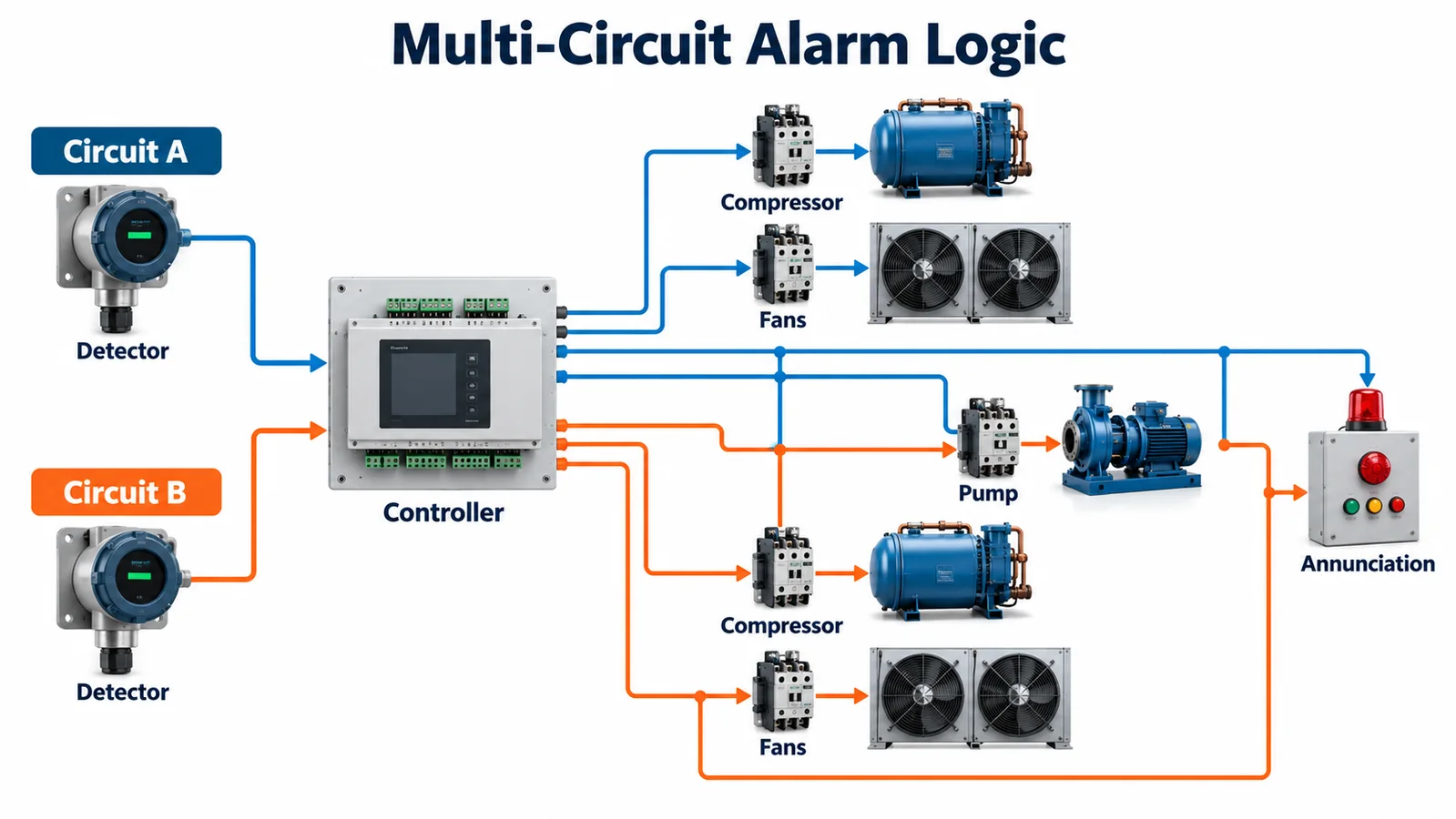
Define how multiple alarms combine. A valid alarm from one circuit may require stopping that compressor while maintaining a fan or pump, but the released safety design may require broader action. Simultaneous alarms, one alarm plus one sensor fault, and communication loss during an alarm all need deterministic priority.
Используйте проверки конфигурации, чтобы убедиться, что вариант хладагента детектора соответствует контуру. Модуль, откалиброванный для другого хладагента, может по-прежнему выдавать правдоподобные данные. Контроль номера детали, электронная идентификация и проверка производства должны предотвратить скрытое несоответствие.
Интерфейс оператора должен различать аварийный сигнал хладагента, неисправность детектора, неисправность связи и неудачные меры по устранению. Эти состояния могут использовать общие защитные меры, но требуют разных ответных мер обслуживания. Одно общее сообщение о неисправности газа замедляет диагностику и побуждает к ненужной замене датчика.
9. Разработайте приоритеты контроллера перед написанием кода
Create a state table covering startup/warm-up, normal, valid alarm, detector fault, stale data, controller communication loss, actuator fault, power interruption and recovery. Define behavior for compressor contactors or drives, condenser fans, pumps, solenoid or shutoff valves if present, heaters, annunciation and remote communication.
Normal capacity control must not override the safety state. If a supervisory controller requests operation while the local controller has latched a refrigerant alarm, the local safety priority must remain deterministic. Similarly, firmware updates, service modes and test functions need controls that cannot leave mitigation disabled.
Define time semantics without inventing universal values: sampling, filtering, persistence, communication timeout, command issuance, feedback deadline and recovery qualification. Derive released values from the applicable requirements and system response budget. Account for sensor tolerance, gas transport, controller processing and actuator motion together.
If the detector reports both concentration and an alarm state, specify how the controller reconciles them. Do not recreate a safety threshold in several software layers without controlled ownership. A single source of released configuration with version traceability reduces divergence.
10. Verify Commands With Physical Feedback
Sending a stop command is not the same as stopping a compressor. A welded contactor, drive fault, stuck relay, failed fan or closed damper can defeat mitigation. Identify which physical results are safety-critical and which feedback signals can demonstrate them.
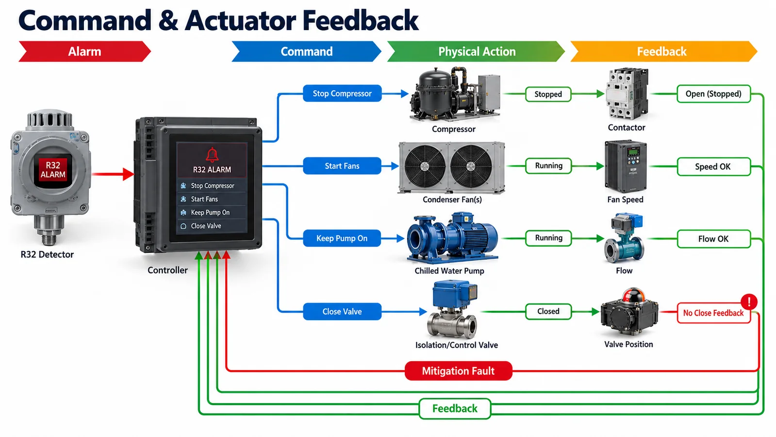
Possible evidence includes auxiliary contacts, drive status, motor current, fan speed, pump flow or valve-position feedback. Each signal has limitations. A contactor auxiliary contact may not prove motor speed; a command echo may not prove the output changed. Select feedback based on the intended physical state and diagnostic coverage.
Define the response when feedback disagrees. Annunciate a mitigation fault, preserve relevant commands, record the event and transition to the released fallback state. Avoid cycling commands rapidly in a way that could re-energize equipment or obscure diagnosis.
Test feedback faults by injection. Disconnect the signal, freeze it, force contradictory values and simulate stuck actuators. Verify controller priority, event logs, remote reporting and recovery. These tests should use the production I/O hardware and firmware, not only a software model.
11. Integrate Startup, Power Loss and Recovery
At power-up, the detector may need time before data are valid. The controller should represent this as warm-up or initialization, not as normal clean air. Define what the chiller may do during that interval. The answer depends on the released product design and requirements.
Brownout and power cycling can reset the detector and controller at different times. Test partial power loss, rapidly repeated resets and communication restart. Ensure stale pre-reset data are not accepted as current. If detector and controller use separate supplies, analyze one-sided power failure.
Recovery from an alarm or fault needs rules. Specify whether reset is automatic or manual, whether sufficient valid data are required, which actuator states are confirmed and whether a service action is needed. Preserve event history across the reset as required for diagnosis.
Where the controller communicates to a building automation system, keep local protection independent of a network connection unless the released architecture explicitly provides equivalent fault tolerance. Loss of supervisory communication should not prevent the local chiller from executing its defined response.
12. Select the Sensor Variant Conservatively
Winsen lists the ZRT512J as an NDIR refrigerant detection module available for refrigerants including R32, with controller-oriented communication options in current product information. Exact supply, output, protocol, response, diagnostics, environmental limits, dimensions, lifetime and qualification evidence must be confirmed from the current controlled datasheet, protocol and project documentation.

For a chiller program, request the complete model code and gas calibration, mechanical drawing, inlet orientation, connector definition, power transient behavior, startup/validity sequence, alarm and fault semantics, communication timing, environmental limits, water/condensation restrictions, vibration evidence, drift/life evidence and change-notification process. If any web-page and controlled-document values differ, the controlled project documents govern.
The sensor supplier can characterize the module under defined exposure. The chiller OEM must validate gas transport to the installed inlet, control response, actuator performance, environmental protection and production consistency. A module does not certify the complete chiller.
13. Build a Production-Intent Validation Matrix
The validation matrix should vary the factors most likely to change response:
| Factor | Example test levels |
|---|---|
| Circuit and source | each circuit; compressor, heat exchanger, valve, joint and service-area sources |
| Operating mode | off, standby, cooling/load states, heating if reversible, transitions |
| Расход воздуха | fan off, staged speeds, full speed, fan fault, representative wind directions |
| Hydronic state | pump off/on, cold fluid, condensation, water leak conditions |
| Enclosure | panel and seal tolerances, production louvers, accessories, module combinations |
| Среда | relevant ambient temperature, humidity, rain/wet and installation conditions |
| Detector | location tolerance, production revisions, relevant aged or conditioned samples |
| Controls | alarm, fault, stale data, power loss, actuator failure and recovery |
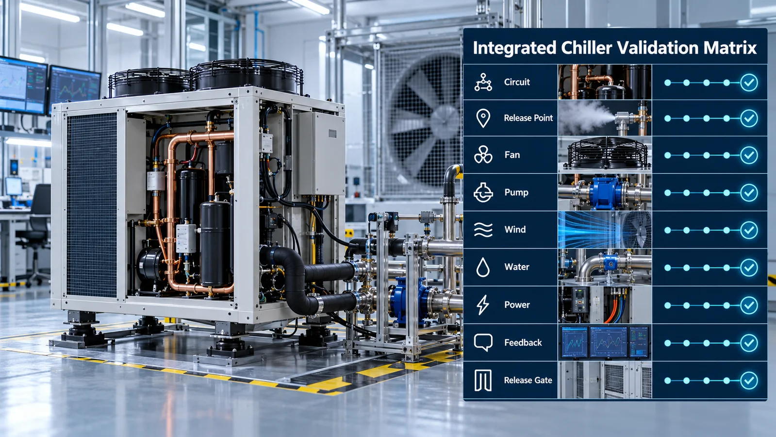
Define release methods and acceptance criteria before execution. Capture detector raw or engineering output, controller state transitions, command timing, actuator feedback and relevant local concentration measurements. Synchronize data and video to explain transport. Repeat limiting cases.
Use production-intent panels, seals, fans, pumps, brackets, harnesses, firmware and software configuration. Open-panel exploratory tests are useful for learning but not for release evidence. Record serials, revisions, calibration status and environmental conditions so results remain reproducible.
14. Preserve the Qualified Design in Production and Service
Manufacturing controls should lock detector part/gas variant, bracket location, inlet clearance, harness route, connector engagement and software configuration. Use fixtures, datums, poka-yoke and electronic checks where appropriate. Prevent sealant, insulation, wire bundles and labels from entering the keep-out zone.
End-of-line checks can verify identity, communication, diagnostics and controller actions. Decide whether production or audit gas exposure is required by the released control plan. Internal self-test cannot detect every blocked-inlet or wrong-location error, so mechanical inspection and periodic functional audits remain important.
Service instructions should protect the inlet during washdown, restore harness routing, confirm the correct replacement variant and run a defined post-service check. If a detector location changes with an enclosure or module option, make that configuration explicit. Field substitutions not covered by qualification should not be implied.
Track alarms, faults, replacements and returned parts. Preserve installation photographs and controller logs where possible. Field data can reveal water paths, vibration wear, configuration errors or transport assumptions that laboratory tests missed.
15. Engineering Release Checklist
Release only when evidence confirms:
- The chiller boundary, R32 charge and applicable controlled requirements are defined.
- Every refrigerant circuit and credible release source maps to demonstrated detector coverage.
- Bulkhead leakage and compartment exchange assumptions are verified.
- Fan staging, wind, pump state, standby and relevant faults are included.
- Water, condensation, wash and hydronic leakage cannot defeat the detector or connector.
- Detector count follows coverage evidence rather than a generic rule.
- Gas identity, circuit mapping, validity, alarm and fault data are unambiguous.
- Controller priority overrides normal load control when required.
- Critical commands have suitable physical feedback and fault response.
- Startup, brownout, stale data and recovery have deterministic behavior.
- The limiting production configuration passes repeatable integrated tests.
- Manufacturing and service controls preserve the qualified location and configuration.
- Product and certification claims are supported by current controlled evidence.
Any “not applicable” should have a recorded rationale. Any “assumed” should become analysis or testing before release.
16. Review Worst Cases and Design Margin
A qualification matrix can produce a pass without revealing how close the system was to failure. After testing, compare concentration-time histories, detector output, command timing and actuator feedback across cases. Identify which combination produced the slowest valid detection, weakest exposure, longest actuator response or most uncertain recovery. That case becomes a design-control reference.
Examine margin in physical terms. If a minor wind change moves the refrigerant plume away from the sensor, the location is fragile. If a small amount of retained water blocks the inlet, drainage is fragile. If mitigation succeeds only when fan speed is at nominal production value, airflow variation needs tighter control or a more robust design. Improving these mechanisms is stronger than merely repeating a favorable test.
Use sensitivity studies to prioritize improvements. Move the detector within the allowed zone, alter a baffle, increase an exchange opening, change harness position or add feedback, then compare the complete response. Document why the final configuration is less sensitive to manufacturing and environmental variation. Avoid optimizing one release point at the expense of another.
The margin review should also cover aging. Detector drift, fan degradation, fouled louvers, pump vibration, coating corrosion and seal changes may move the system toward the boundary. Use controlled aged or conditioned components where the qualification plan requires them. Ensure maintenance instructions preserve the airflow and drainage features assumed by the safety design.
Finally, assign regression triggers. Changes to fan, grille, compressor, refrigerant circuit, partition, hydronic insulation, sensor, bracket, firmware or threshold configuration should prompt a documented assessment. The team should know which limiting tests to repeat, rather than rediscovering the coverage argument after a late product change.
Заключение
R32 detection in a small chiller is a coupled mechanical and controls problem. Compartment boundaries, wind, condenser fans, pumps, water, circuit mapping and actuator feedback determine whether a detector can support the intended response. The engineering target is a verified chain from credible release to controlled physical state, maintained through manufacturing and service.
Для технического анализа предоставьте хладагент и заправку в каждом контуре, чертежи цепей/корпусов, условия установки, состояния вентиляторов и насосов, возможные места расположения, интерфейс контроллера, предполагаемые действия при тревоге/неисправности, сигналы обратной связи, годовой объем и целевой рынок сертификации. Эта информация позволяет обсудить детектор, опираясь на реальный охладитель, а не на выбор общего модуля.
Ссылки
- UL Solutions — Проверка систем обнаружения хладагента в оборудовании HVAC
- Решения UL — обновленные требования к системам обнаружения хладагента
- Решения UL — Реакция датчиков в системах HVAC
- AHRI — Инициатива по исследованию легковоспламеняющихся хладагентов
- AHRTI 9009 — Обнаружение утечек хладагентов A2L в оборудовании HVACR
- Коупленд — Решения для продуктов A2L
- Winsen — ZRT512J Refrigerant Detection Module
