
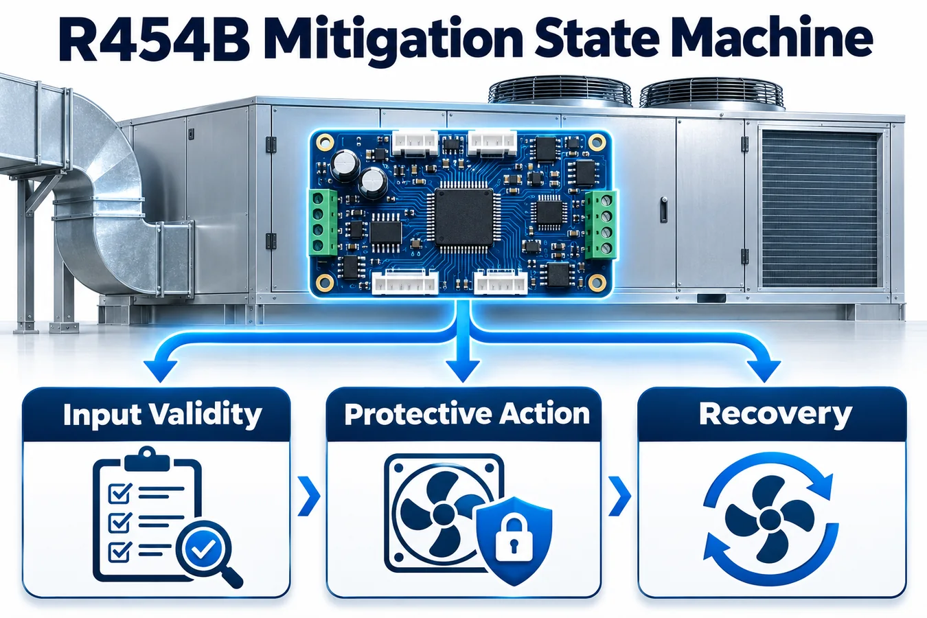
When a refrigerant detector asserts an alarm, the equipment controller must reconcile existing calls, supervise the requested response and decide when ordinary operation can resume. A deterministic R454B mitigation control state machine makes those decisions visible. Each transition has an initiating condition, an owner, observable outputs and a defined outcome when an expected response fails to appear.
This guide uses an illustrative ducted platform with an indoor detector, an equipment controller, a blower and a separately controlled refrigerant circuit. It assumes the OEM has already defined its required mitigation actions, response bounds, restoration policy and equipment constraints. The examples show how to turn those requirements into testable logic. Use the certification basis, equipment architecture and controlled interface specifications for the exact model to determine the requirements that populate the design. UL Solutions describes equipment-level detection and automatic response as parts of the integral detection system. UL Solutions overview of integral refrigerant detection
1. Specify the control contract before drawing the states
Write an input and output contract that spans the detector, mitigation decision and physical equipment actions. Identify which interface carries an asserted event, which component evaluates validity, where the equipment interlocks are enforced and which component supplies evidence of actuator response. Include ordinary demand signals that may be present during the response. Put an owner beside each signal so ambiguity about meaning has somewhere to be resolved.
For the illustrative platform, assume the detector reports an event and readiness status, the indoor controller owns operating permission, and a separate board owns the compressor command. The indoor controller requests the defined airflow and observes a form of airflow proof selected by the OEM. Treat release authorization, actual compressor state and airflow confirmation as distinct signals. If a platform observes only a subset, document what the available signal can establish and how the remaining behavior is evaluated.
Start with invariants. For this example, an active or retained event suppresses the ordinary operating permissions selected by the OEM. A clearing indication alone cannot restore those permissions. A proof deadline that expires sends the controller to a defined restricted state. These statements describe observable behavior across all entry paths, including a transition that happens during a board restart.
2. Normalize input meaning and freshness
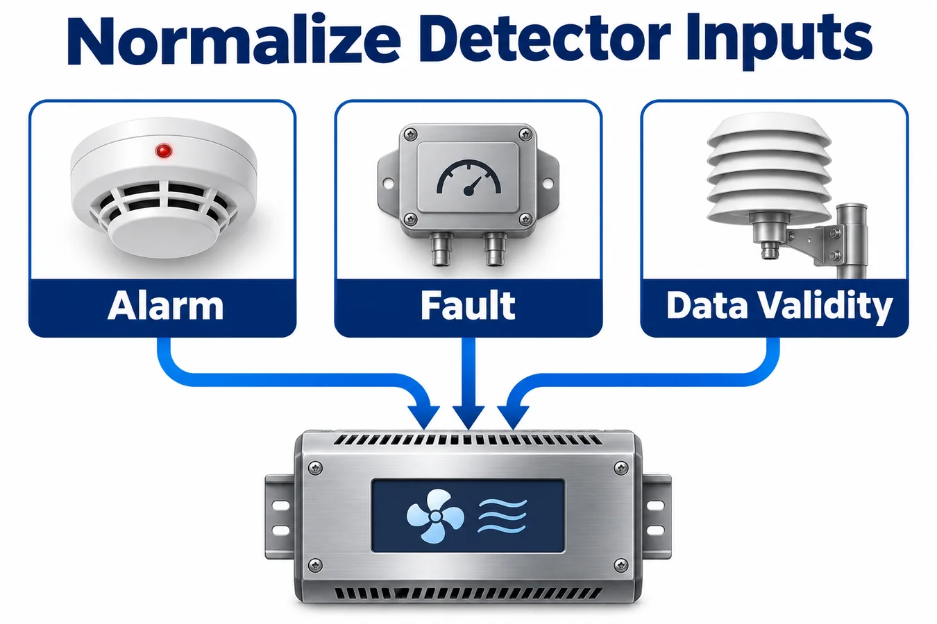
Translate hardware signals or messages into a common form before the policy evaluates them. A useful input record includes the interpreted condition, source, validity and freshness, along with the time at which the value became eligible for a decision. For a detector event input, distinguish a current clear indication from an unavailable or indeterminate input. A stream of syntactically valid messages can still carry an unusable value if the device is starting, the revision is incompatible or the measurement is stale.
For a discrete input, document its asserted polarity, power relationship and the assumptions needed to interpret both signal levels. For a digital input, specify the allowed representation, report cadence, initialization behavior and when an old value expires. If a digital measurement is part of the OEM decision, keep the units and scale attached to the value throughout the conversion. The state machine should receive explicit eligibility and status information so the decision does not depend on a particular transport encoding.
Keep fault interpretation separate from event memory. If the last accepted event was active and the detector link disappears, the link status changes while the retained event stays active under the example policy. If communications return, current device readiness and freshness must be re-established before clear data can count toward recovery. This prevents a communications recovery from acting like an equipment reset.
3. Separate operating policy from actuator progress
Use state names that explain what behavior the equipment owes. A small supervisory set might include INITIALIZING, AVAILABLE, MITIGATING, RESTRICTED and RECOVERY REVIEW. Track response progress through explicit flags or substates inside MITIGATING when the sequence needs to distinguish commanding, waiting for proof and maintaining a confirmed response. Write down which parts of the state are retained and which are recomputed after startup.
Avoid building a distinct top-level state for each combination of thermostat call, blower phase and diagnostic observation. The operating state should represent control authority. Auxiliary facts carry information needed by an output rule, proof guard or recorder. This separation helps a reviewer see whether an incoming heat request can affect mitigation outputs without scanning a large set of mode combinations.
For each state, define the output behavior that remains continuously true while it is active. Entry actions can perform tasks such as stamping a transaction, but the required output levels need an owner after entry completes. If one routine sets mitigation airflow at entry and a normal demand handler writes the same output on its next update, the diagram and the hardware can diverge. An output arbiter driven by state and approved interlocks provides a single place to review those decisions.
4. Resolve simultaneous inputs in one evaluation
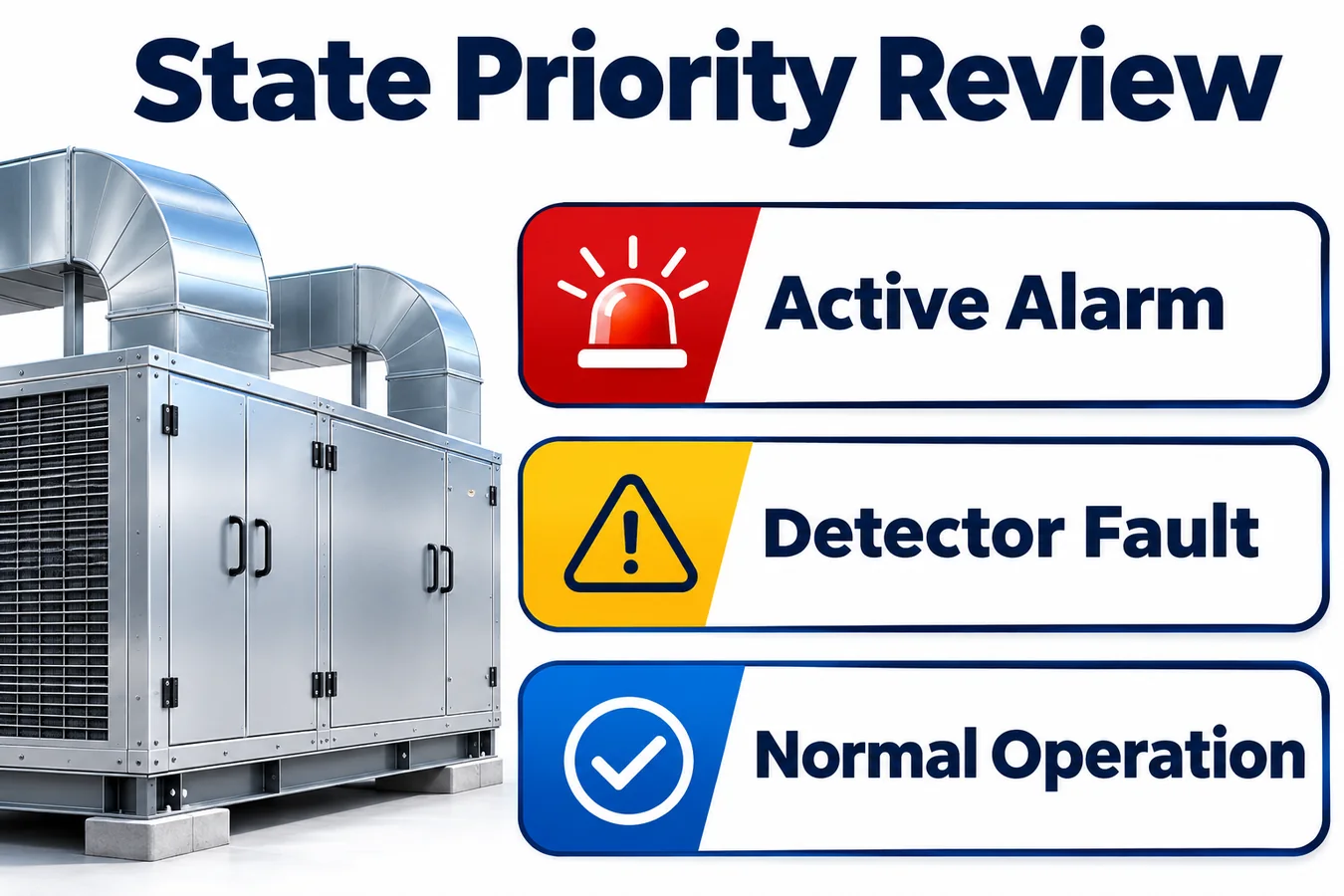
Write a precedence table for the events that can compete. Include a newly accepted detection event and a reset request in the same evaluation, a late proof arriving when the proof deadline expires, and a demand arriving while the detector is being initialized. Determine the snapshot boundary and evaluate compatible observations together. If a controller samples different sources in separate tasks, define how it obtains a consistent decision snapshot and how a safety-relevant asynchronous signal affects that design.
In this example, an active event takes precedence over reset authorization and ordinary requests. Applicable equipment interlocks constrain the physical outputs under the documented policy. A late proof is treated according to an explicit timestamp boundary. The design states whether proof at the deadline qualifies, and the regression suite exercises that equality case. Avoid an accidental policy based on interrupt ordering or queue insertion order.
Publish one set of resolved outputs per decision cycle. Downstream application tasks should receive the committed outputs and state, so they observe a coherent result. If the controller uses hardware signal paths that can change outputs independently, put those paths on the same timing diagram and reconcile them in the interface contract. The actual output at the equipment boundary is what the end-to-end evidence needs to establish.
5. Build a transition matrix with explicit guards
The rows below assume a single supervisory controller. An equipment implementation adds the exact output map, requirements identifiers, timing criteria and authority rules that apply to its platform. Each output label stands for the actions specified in the released control policy.
| Current state | Eligible input or guard | Next state | Observable outcome |
|---|---|---|---|
| INITIALIZING | Detector and dependent interfaces eligible, with the startup review complete | AVAILABLE | Ordinary permissions become available under current equipment interlocks |
| INITIALIZING or AVAILABLE | Accepted event or active retained event | MITIGATING | Event retained, mitigation outputs applied and proof supervision started as appropriate |
| AVAILABLE | Required input unavailable | RESTRICTED | Restricted output map applied under the approved unavailable-input policy |
| MITIGATING | Required proof observed within its guard | MITIGATING | Confirmed progress recorded and proof supervised as required |
| MITIGATING | Required proof deadline expires | RESTRICTED | Proof outcome recorded, event retained and restricted output map applied |
| MITIGATING or RESTRICTED | Recovery eligibility conditions satisfied | RECOVERY REVIEW | Required restrictions remain pending recovery disposition |
| RECOVERY REVIEW | Authorized recovery and every release condition still valid | AVAILABLE | Retention handled per policy and ordinary requests reevaluated |
| RECOVERY REVIEW | Active event or loss of eligibility | MITIGATING or RESTRICTED, per cause | Recovery authorization invalidated and applicable outputs maintained |
Complete the unlisted cases in the controlled transition specification. Holding state can be a deliberate outcome with defined outputs and timer behavior. Give initialization paths the same attention as ordinary steady-state transitions. Specify what happens when startup conditions remain incomplete and when required proof is already present at entry, as can happen when the fan was running before the event.
6. Define proof against the physical response
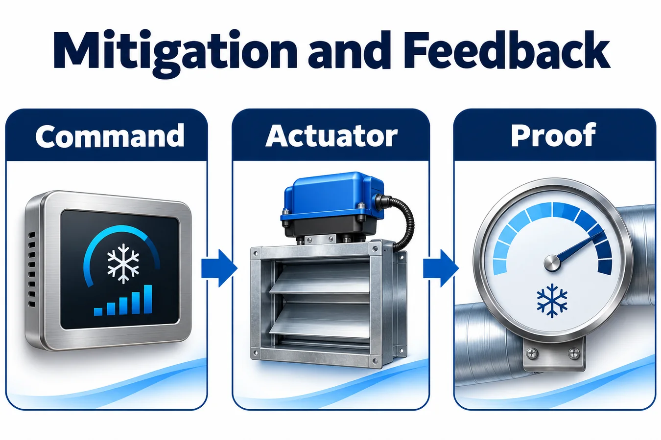
Draw the event timeline from accepted detector condition through output request, device acceptance, actuator response and the resulting proof. Distinguish a command bit, a receiving-board acknowledgment and a physical observation. A board can acknowledge a fan command while the motor is ramping or while a restriction limits actual flow. Decide which evidence applies to each action and record its limitations in the interface contract.
For an already running blower, define whether its current feedback is eligible immediately or must demonstrate the required mitigation operating condition after the command changes. If the proof is sampled before the event, decide what freshness and operating-mode information makes that observation admissible. If a compressor is already stopped, distinguish its observed state from the continued enforceability of the required inhibition while an ordinary call persists.
Define separate timing landmarks for sensor event receipt, controller acceptance, output assertion and proof. Give each measured interval a requirement reference. A recorded total time can reveal a failed bound, but the individual landmarks help identify whether the consumed time belongs to signal transport, scheduling, an actuator ramp or the proof filter. Use the same landmarks in the code, lab trace and review checklist.
7. Tie timers to the event that gives them meaning
Define where each timer starts, the clock used to evaluate it, and the events that cancel, retain or restart it. A proof timer may belong to a particular issued request. A hold period may start when mitigation outputs become effective or at another landmark specified by the equipment requirements. A recovery dwell may depend on the continuous eligibility of a clear indication. Draw these separately when they measure different things.
Use a time source appropriate to the execution environment. If clock ticks wrap or an application task can be delayed, show how comparisons behave across those conditions. Consider how shared communication traffic and long diagnostic activities affect the interval between accepted observations and output writes. Include the maximum scheduling and I/O delays justified by the implementation in the timing budget. Bench evidence from an unloaded controller establishes only the tested case.
Write one test that repeats an active event during MITIGATING and one that changes an unrelated ordinary demand during the same phase. Inspect whether either restarts the proof deadline. If the policy calls for a restart, make the event that grants it explicit. The proof record should make clear which command and which timer window a response belongs to.
8. Give recovery its own authorization rule
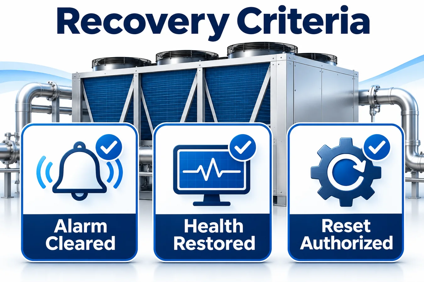
Separate clear detection, recovery eligibility and permission to restore operation. A clearing report may begin a recovery review when it is current and valid, while the retained event and required restrictions remain in force. The policy must define which evidence stays valid throughout review and what a renewed event or unavailable input does to eligibility. Where the approved design allows a recovery command, specify the source and how the command becomes eligible.
Consider a user interface that holds a reset bit until the controller responds. If a reset was requested before eligibility and remains present when all other conditions become true, determine whether the controller requires a new authorized action. If a local and a remote request can arrive together, identify their authority and how the decision is recorded. A distinct authorization event with a defined lifetime is easier to test than a continuously asserted permissive.
An ordinary request may still be present when the equipment leaves RECOVERY REVIEW. Specify how the equipment reevaluates this request against present interlocks, operating conditions and the approved restart sequence. Tie the release of retained information to the successful recovery disposition. Capture the prior state and observations before advancing so a trace can show what justified restoration.
9. Model power interruptions as transitions
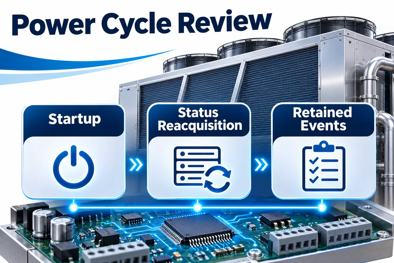
Test independent reset and outage cases for the detector, decision controller and actuator-owning board when they can lose power separately. Draw the outputs visible during power loss, startup and application initialization. A controller restart includes an electrical interval before policy code runs. Hardware default levels, relay behavior and receiving-board interpretation determine the physical outputs in that interval.
For the illustrative platform, assume the approved policy requires an active event to survive a decision-controller reset. The specification must define which record is retained, how it is validated and what the equipment does when retention is unreadable. Test an interrupted update at a point where the controller could otherwise lose the only copy of the event. During boot, require new readiness and status evidence from dependent boards before treating their old state as current.
Distinguish a full outage from an indoor-board restart with the outdoor board still operating. In the latter case, verify which outputs the outdoor board sees while the indoor board boots and how it reacts to stale commands or a dropped signal. Compare the reconstructed state with the state the equipment must observe at its interfaces. Test the sequence at several points, including between command and proof, during confirmation and during recovery review.
10. Inject faults at the control boundaries
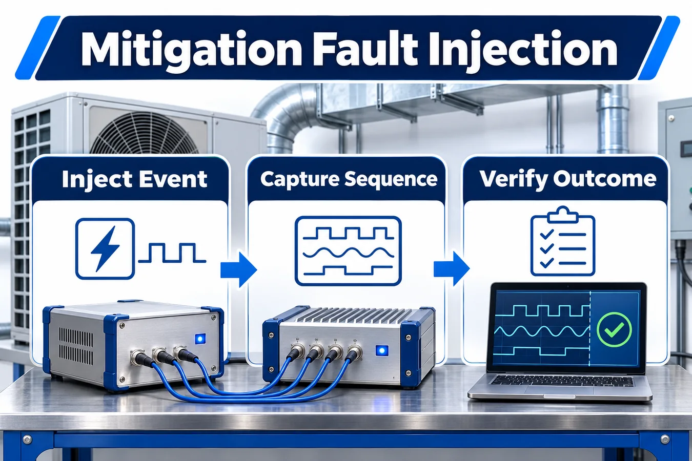
Run repeatable tests that interrupt or delay events at the point where the state machine observes them. Begin with a reference trace for a complete response, then drop the detector input after an accepted event, delay proof beyond its guard and restart one board during recovery review. Observe output continuity, retained status, timer behavior and the first available recovery path. The purpose here is to verify how the control logic responds to an unavailable or unexpected observation.
Test combinations of events as well as isolated transitions. Pair a renewed alarm with a reset, a stale clear with a thermostat call, and disappearing proof with an actuator board restart. Use precise scheduling around the boundary when ordering affects eligibility. Record which data was injected, which data came from actual hardware and how the injection mechanism affects timestamps. This makes a failed test repeatable and an accepted test auditable.
Include a run where an interface transmits a valid acknowledgment but the equipment does not produce the expected physical result. Confirm that the controller evaluates the specified proof rather than advancing on receipt of the acknowledgment alone. Inspect both the retained decision and the actual equipment outputs when the controller moves to its defined restricted behavior.
11. Walk a complete example trace at design review
Assume a cooling call is present. The detector reports an eligible event, the controller records it, and the state changes from AVAILABLE to MITIGATING. The decision emits the specified compressor permission change and blower request in the ordering required by the approved equipment design. The reviewer examines the controller commit, the receiving-board inputs and the physical observations on one timeline.
In the first trial, the blower’s receiver acknowledges the request and physical proof follows within the permitted window. Later, the detector reports clear while the cooling call remains present. Confirm that the controller enters or remains in the prescribed hold or review phase. Apply authorized recovery only after the defined eligibility conditions are met, then verify that ordinary cooling follows the approved restart rules. The trace should capture the time and condition that allowed each change.
In the second trial, send the same acknowledgment but withhold the proof. The supervisor must execute the released proof-failure behavior and retain the event according to policy. Restore valid communications and observe whether an old clear or reset from before the interruption can qualify. The control review can now compare traces whose initial commands look alike but whose actual response outcomes differ.
12. Define the boundary between controller and receiving board
When two boards participate in mitigation, a message can describe a request, receipt of a request, or the current equipment condition. Treat those as separate observations. In the illustrative design, the indoor controller may send an inhibit request and receive a reply from the outdoor board. If the reply only confirms message receipt, the indoor controller has evidence about transport. The equipment program must separately determine what confirms enforcement of the request and what freshness applies to that confirmation.
Specify how a response belongs to a particular command. In a design with sequence identifiers, test what happens when the receiver repeats its most recent reply after a new request. In a design based on signal levels, test what the receiving board observes during the interval when the sender changes mode or restarts. Establish how to identify a new decision after power returns, especially when the receiving board remains active. Use the contract to decide which observations survive a mode change and which must be obtained again.
Give each board a repeatable integration scenario. For example, interrupt the indoor controller after it asserts the request but before it records proof, while preserving power to the outdoor board. Capture the last request issued before the restart, the output visible during boot, the first valid status from the receiver and the point where the indoor controller resumes supervision. The trace should show how the approved restrictions remain represented through the handoff.
Maintain the same definitions across engineering teams and suppliers. If an interface name such as “inhibit active” is ambiguous, specify whether it reports the input accepted, a permission withheld, or an observed device state. Include the interpretation in the test record. A later change to the receiver can then be reviewed for its effect on the original evidence, even when the interface name and connector remain familiar.
13. Control the implementation and evidence together
Use a traceability matrix from equipment requirement to transition guard, output rule, test stimulus and observed result. A timing change in detector polling can affect freshness, proof evaluation and recovery eligibility even if the supervisor’s state diagram remains unchanged. Link the interface definition and configuration values to the same release as the control implementation.
Review what each layer of testing can establish. A logic harness can exercise precedence and invalid combinations reproducibly. A controller bench with representative boards can expose boot timing, polling interaction and output default behavior. Equipment tests demonstrate physical response within the assessed configuration. Record hardware and firmware revisions, detector configuration, test arrangement and measurement basis. Assign an owner to every assumption that comes from another board or team.
Keep evidence reviewable after a firmware revision. Retain reference traces for the critical boundaries and define what changes trigger repetition. Useful triggers include a change to startup defaults, elapsed-time handling, interface freshness, physical proof, or which component owns release permission. The trace is also a practical onboarding tool for engineers maintaining the equipment years after qualification.
14. Evaluate the ZRT512C-A as a detector candidate

Winsen lists R454B among the target refrigerants for the ZRT512C-A. Evaluate a sample of the exact orderable R454B configuration against the released controller requirements. Ask for a controlled interface specification, message or signal semantics, startup behavior, validity indications and revision identification. Confirm how the chosen configuration distinguishes an eligible measurement from initialization, loss of availability and restored operation. Installed proof and recovery behavior remain decisions for the equipment program. Winsen ZRT512C-A 製品ページ
15. Frequently asked questions
Should the state machine accept the detector’s clear report immediately?
The input layer may accept an eligible clear report when it meets the interface contract. Recovery is a separate equipment decision. The approved policy specifies how long the evidence must remain valid, which restrictions still apply and how recovery is authorized. Represent those facts explicitly so an input update alone cannot accidentally restore permissions.
Can acknowledgment stand in for proof?
An acknowledgment establishes whatever the receiver’s contract says it acknowledges. In a platform where the criterion is physical airflow or another physical outcome, use evidence appropriate to that criterion. Document any supporting relationship between the interface status and the physical response. Verify it in the relevant modes and challenge it when a command is accepted but equipment response is unavailable.
Who owns recovery in equipment with several controllers?
Choose an authority in the system requirements and identify how other controllers obtain and validate its disposition. Some architectures share action ownership, with separate boards granting individual equipment permissions. State which component decides that all conditions are satisfied and how the design handles inconsistent, unavailable or stale status at that boundary.
How should the controller handle a detection event during initialization?
Define which inputs are eligible in each startup phase, then specify the precedence of an accepted or retained event. Validate the actual equipment outputs before software finishes initialization and throughout recovery from a partial restart. Include power and control dependencies from the boards that participate in the response.
16. Request an OEM interface and validation review
Send Winsen the target equipment architecture, exact R454B detector configuration under consideration, supply and interface assumptions, proposed normalized inputs, and a draft transition table. Include the response milestones your equipment needs to observe and the startup and interruption cases the lab intends to reproduce. Ask for controlled documentation and representative samples for the interface that will be evaluated.
Use the review to settle the detector-side definitions needed for integration. Confirm readiness, validity and event semantics, when observations become fresh, and what the controller sees during power transitions. Attach the agreed definitions to the equipment specification so firmware and validation use the same expectations when they review recovery and proof. Winsen OEM contact
Review the ZRT512C-A product listing そして submit the equipment details for an OEM integration review。
