
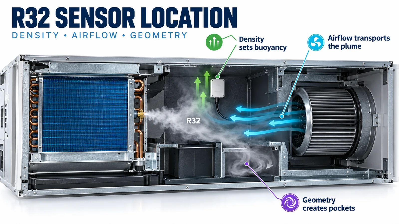
“R32 is heavier than air, so install the detector at the lowest point” is an incomplete design method. Density affects buoyancy after release, but a real leak also has momentum, mixes with surrounding air, encounters the coil and drain pan, and may be transported by a blower. The result is a three-dimensional concentration field that changes with time and equipment state.
For HVAC equipment engineers, the useful question is: which candidate position reaches the required concentration soon enough in every credible scenario? Answering it requires physics-informed screening followed by measurement in the actual enclosure.
Density gives a tendency, not a complete trajectory
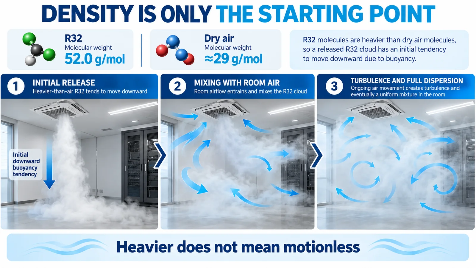
NIST lists the molecular weight of R32, or difluoromethane, as about 52.02 g/mol. Dry air has an average molecular weight of roughly 29 g/mol, so a sufficiently cool, concentrated R32-rich mixture tends to move downward relative to surrounding air. That observation is useful when looking for low-velocity accumulation zones.
It does not mean every molecule immediately falls to the lowest corner. A refrigerant cloud is a gas mixture, not a layer of liquid. Temperature differences, entrainment, diffusion, turbulence and forced airflow can oppose or overwhelm the initial buoyancy tendency. Use density to define hypotheses, then test them.
Leak momentum controls the first seconds
A pressurized release through a crack, fitting or tube defect forms a jet. Its direction and velocity initially govern where the refrigerant travels. The jet entrains surrounding air, which increases total plume volume while lowering concentration. If it strikes a coil fin, cabinet wall or baffle, it spreads along that surface or redirects into an adjacent compartment.
Rapid expansion and vaporization can also cool the release and nearby surfaces. The combined jet, thermal and buoyancy effects mean that a detector directly below the source may not be the first point to see a meaningful concentration. Candidate positions should be evaluated against realistic release directions and not only a diffuse source.

Blower state rewrites the concentration field
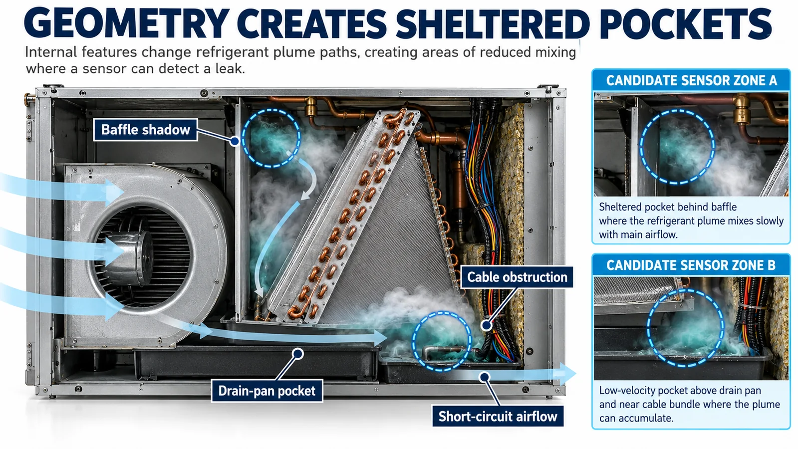
When the fan is off, a local pocket may form behind the coil, above a drain pan lip or in a lower cabinet compartment. When the fan starts, that pocket can be diluted and transported. A sensor close to the source may see a lower peak, while a downstream sensor may respond sooner.
Mitigation airflow introduces a second fan-on condition. It may be different from normal cooling airflow in speed, damper position or flow direction. Qualification should therefore include fan off, normal fan operation and the commanded mitigation state defined by the equipment safety strategy. Filter loading and external static pressure should be represented when they materially change the flow field.

Cabinet geometry creates pockets and bypass paths
Sheet-metal partitions, coil frames, drain pans, insulation, harnesses and control boxes create separated flow regions. A baffle shadow can retain a concentrated plume. A narrow gap can accelerate a bypass stream. A large wire bundle can block the route between a leak source and a sensing inlet.
These features are easy to miss in a simplified computational model or an open-panel bench test. Evaluate the production-intent assembly with the intended insulation, harness clips, filters and covers installed. Preserve clearance around the sensing inlet in the drawing and bill of materials so later routing changes do not invalidate the test result.
Orientation changes gravity, drainage and airflow together
Rotating an air handler from upflow to horizontal changes more than “down.” It changes which drain pan is active, which surfaces intercept the leak jet, where condensate can travel and how the blower draws from the coil compartment. A position qualified in one orientation cannot be assumed equivalent in another.
Where an equipment family permits several orientations, define a controlled sensor location for each configuration. Installation instructions should identify the bracket, sensing-face direction and harness route. Production and field checks should make an incorrect position visible.
Build a four-part scenario matrix
A practical validation matrix crosses four sets:
| Scenario set | Include | Hvorfor det betyder noget |
|---|---|---|
| Leak sources | distributor, headers, return bends, joints, service tubing | the source and release direction set the initial plume |
| Fan states | off, normal operation, specified mitigation state | forced airflow transports and dilutes refrigerant |
| Unit orientations | every approved upflow, downflow or horizontal arrangement | gravity, drainage and internal flow paths rotate |
| Panel conditions | intended operating covers, filters and seals | enclosure leakage and recirculation change |
Add temperature, humidity and airflow extremes that are relevant to the product specification. The slowest credible detection case becomes the placement design case.

Convert the physics into candidate-location rules
During concept screening, prefer locations that:
- lie on plume paths shared by several credible sources;
- retain adequate concentration in both fan-off and relevant fan-on states;
- remain outside condensate, cleaning-fluid and drain-overflow paths;
- provide datasheet-required inlet clearance and mounting attitude;
- avoid direct impingement that could contaminate or thermally shock the sensor;
- allow stable wiring, diagnostics and service access;
- can be reproduced across production units with controlled brackets and harness lengths.
Reject any location that works only because a prototype panel, insulation piece or cable route differs from the released design.
Measure concentration versus time at every candidate
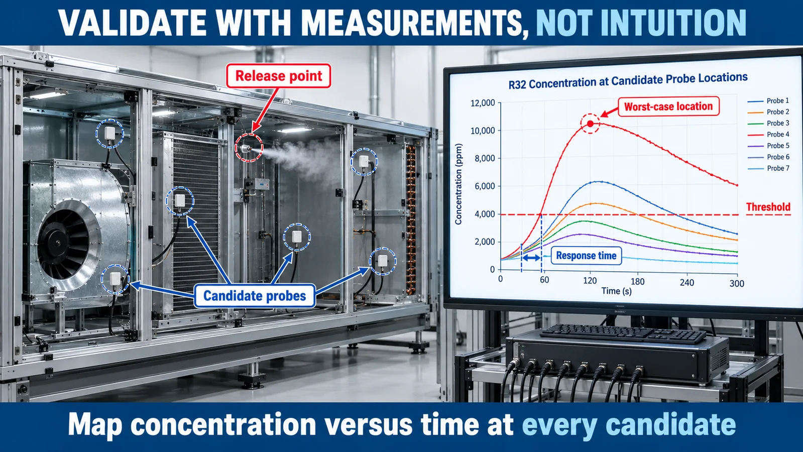
Place calibrated reference probes at the candidate points and at locations likely to represent worst-case accumulation. Conduct controlled releases at documented rates or quantities. Record the reference concentration, installed sensor output, blower command, controller state and time to each event.
The objective is not to create the highest possible local reading. It is to demonstrate reliable, timely response across the complete scenario matrix without nuisance behavior in normal operation. Review the response distribution and repeatability, then preserve margin for production tolerance, ageing and environmental variation as required by the equipment qualification plan.
Treat sensor fault and gas alarm as different events
An R32 alarm indicates that the sensing channel has detected the defined refrigerant condition. A sensor fault indicates that the safety channel may be unavailable or unreliable. The controller should separately handle communication timeout, implausible output, supply fault and any device-specific diagnostic.
Define startup and warm-up behavior, debounce or confirmation logic, latching, reset and service indication. Validate the complete timing chain from release to detector output, controller decision and mitigation result. A fast component response cannot compensate for a location that the plume reaches late.
Choose the sensing technology and interface for the system
AHRI research has examined both infrared and metal-oxide-semiconductor approaches for refrigerant detection. Technology selection should consider target refrigerant, selectivity, environmental range, expected contaminants, response and recovery, lifetime, diagnostics, power and controller interface. Placement validation remains necessary for either principle.
Winsen’s MH-Z1542B-R32 is listed in the current product export as an NDIR R32 sensor with UART. The ZRT510 R32 module is also listed as NDIR, while the ZP201 is listed as a semiconductor R32 module with TTL-level output. Confirm the exact variant, interface, dimensions and current qualification evidence against the controlled datasheet before selection.

For related system choices, read Sådan vælger du en kølemiddelsensor til A2L HVAC-udstyr og UL 60335-2-40 Kølemiddeldetektionssensorkrav.
Engineering review checklist and next step
Before freezing the location, confirm that every credible source, fan state, approved orientation and intended enclosure condition is represented; the detector remains dry and unobstructed; alarm and fault paths are distinct; and the slowest response meets the equipment requirement with margin.
For a project review, send the refrigerant and charge, cabinet and coil drawings, orientation set, airflow range, controller interface, alarm target, environmental limits, annual volume and certification market. Contact Winsen to discuss the sensing approach and validation inputs.
Referencer
- NIST Chemistry WebBook: Difluoromethane (R32)
- AHRI Flammable Refrigerants Research Initiative
- AHRTI 9009: Sensor Technology Assessment and Integration
- AHRTI/UL Technical Report: Sensor Response in an R32 Air Handler
- UL Solutions: Inspecting Refrigerant Detection Systems in HVAC Equipment
- U.S. EPA SNAP: Residential and Light Commercial Air Conditioning and Heat Pumps
