

There is no defensible universal answer such as “one refrigerant sensor per coil.” The correct count depends on whether refrigerant from every credible release can reach a qualified sensing point, in time, under every required operating condition. Coils, headers, partitions, dampers, fans and valves determine the paths; the final production-intent equipment test confirms them.
UL Solutions notes that equipment with multiple indoor coils typically has multiple sensors, but “typically” is not a substitute for an equipment-specific coverage study. This guide gives engineers a method to determine the candidate count for R32 or R454B equipment and to convert that decision into traceable validation evidence.
Count independent gas paths, not just coils
Start with every refrigerant-bearing source: coil headers, return bends, distributors, joints, valve blocks and field connections. Then draw the enclosure volumes and openings that connect each source to candidate sensing zones. Two coils in a genuinely common plenum may share a path; two adjacent coils separated by a pan, baffle or closed damper may not.
The first sensor count is a hypothesis. If one point can cover all sources and states, test it. If the paths remain separate, add candidates near the unserved regions. The released count is the smallest architecture that meets all applicable response, fault and reliability requirements—not the smallest number that looks economical on a drawing.

Define refrigerant-inventory boundaries
Sensor coverage must be related to the refrigerant that can actually enter each compartment. Map valves, check devices and piping volumes, including residual charge after an isolation command. A coil that is nominally off may remain connected to a shared circuit. A closed branch valve may reduce future flow without eliminating the refrigerant already trapped downstream.
Document maximum applicable charge, permitted coil combinations and branch configurations. If field selection changes the connected inventory, make the sensor architecture part of the configuration control rather than assuming the factory’s minimum arrangement applies to every installation.
Identify partitions and leakage between compartments
Air-handling equipment often contains structural partitions, filter racks, drain pans, access-panel seams and insulation blocks. Some are intentionally leaky; others become nearly sealed after installation. A small opening that equalizes pressure may still be too slow or too remote to provide a qualified gas path.
Measure production clearances and evaluate tolerance extremes. Include optional accessories and service panels. Do not drill test-only holes or remove covers unless that condition is part of the approved equipment. The concentration field must represent the product customers receive.
When one sensor can be a candidate
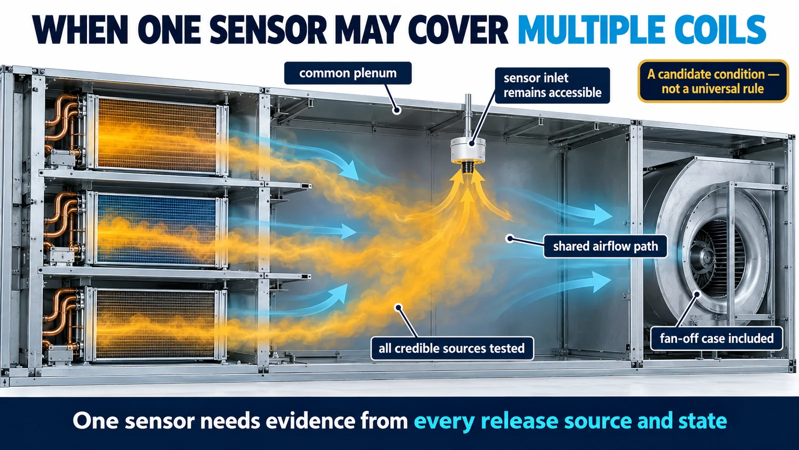
One sensor may be a reasonable candidate when all credible release points discharge into a common, continuously connected plenum and the selected location intercepts those paths in every required state. The evidence should cover fan on and off, relevant airflow ranges, heating or cooling modes, startup, shutdown and any damper or valve positions.
The word “common” needs proof. A fan can pull gas away from the candidate, while fan-off buoyancy can create separate low pockets. The final sensor housing, inlet, bracket and nearby obstructions must be present during testing. Passing one high-rate release at nominal airflow does not establish coverage.
When multiple sensing points are needed
Multiple sensors become the stronger architecture when coils occupy separated compartments, release paths are blocked, branches can operate independently, or no single location covers both forced-air and stagnant states. Dedicated channels can also preserve which section generated the event and support more precise service diagnostics.
Do not place additional devices merely for visual symmetry. Each sensor needs a defined coverage responsibility and fault response. Conversely, do not combine channels by averaging their readings; averaging can dilute a local alarm. The equipment logic should evaluate each safety-relevant channel according to the certified design.

Fan states can reverse the best location
With the fan off, gravity, enclosure leakage and thermal effects may dominate. With the fan on, forced flow can carry refrigerant across one coil, through a bypass or out of the section before a low-mounted sensor responds. Low and high airflow, dirty-filter conditions and fan coast-down can produce different limiting paths.
Record commanded and actual fan state. If mitigation depends on fan operation, validate both the detector response before the command and the concentration field after it. A stalled or disconnected fan should not be represented by the normal airflow trace.
Damper and valve positions create new configurations
Multi-coil units may use face-and-bypass dampers, zoning dampers, refrigerant valves or staged circuits. Each permitted position can connect or isolate gas paths. A sensor that covers Coil A while a damper is open may be shielded when the damper closes; a valve may change which source remains pressurized.
List stable states and transitions. Include loss-of-power positions, actuator faults and feedback mismatch. The test matrix can group configurations only when an engineering analysis shows they have equivalent or less challenging transport and refrigerant inventory.

Installation orientation changes the count question
Upflow, downflow, horizontal-left and horizontal-right installations rotate cabinet features relative to gravity. Separate low regions can appear, drain pans change position and a previously connected path can become a pocket. A common sensor count is acceptable only if the same architecture is qualified in every approved orientation.
If the design uses orientation-specific sensor brackets, control them in the bill of material and field-conversion instructions. Include connector and harness routing so an installer cannot leave a detector in the location for a different orientation.
Build a release-point coverage matrix
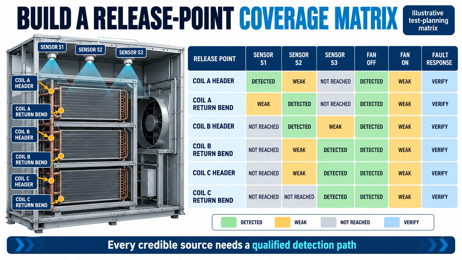
Use rows for credible release sources and columns for candidate sensors, operating states and fault cases. Record whether each source produces qualified detection, marginal response or no meaningful path. “Marginal” cases should trigger design improvement or expanded repeat testing, not a convenient average.
The infographic below is illustrative; its colored cells are not product performance data. Your matrix should contain the actual reference concentration, detector trace, timing criterion, environmental condition, equipment revision and pass/fail basis for every tested case.
Distinguish coverage from redundancy
Two sensors in different compartments may both be required for coverage; they are not redundant. Two sensors sampling the same qualified volume may provide redundancy, but only if their independence, diagnostics, common-cause failures and decision logic are evaluated. Calling devices “redundant” does not justify ignoring a blocked gas path.
Define whether a single sensor fault permits continued operation, forces a controlled state, or requires service. Include power, wiring, communications and controller input faults. A fault channel must not look like a healthy low concentration.
Validate worst-case release and operating combinations
Use production-intent units and controlled releases at each credible source. Include the applicable refrigerant, charge, release method, environmental range, filters, covers, insulation, drains, fans, dampers, valves and controller software. Instrument a reference concentration without altering the local flow.
Repeat the slowest and most variable cases across manufacturing and environmental corners. Record detector output, alarm transition, mitigation command, actuator feedback and recovery. A qualified count is supported by the complete matrix, not by the fastest representative test.
Freeze the design and trigger focused re-evaluation
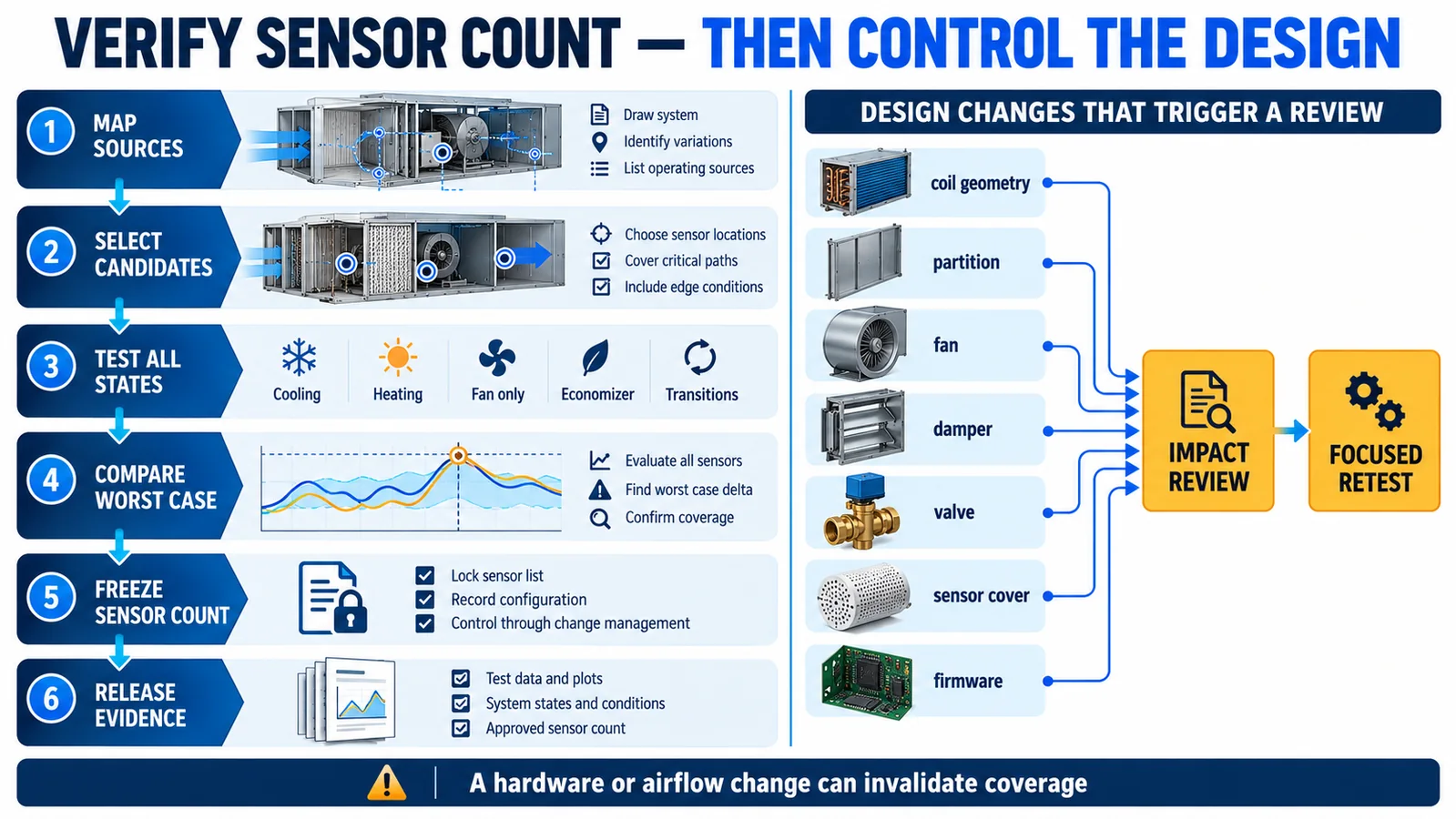
Once evidence supports the sensor count, freeze the sensor model, bracket, inlet orientation, harness, controller mapping, firmware and inspection criteria. Retain raw test data and configuration photos. End-of-line checks should detect missing, swapped or incorrectly addressed channels.
Changes to coil geometry, partitions, drain parts, fan curves, dampers, valves, sensor covers or software need an impact review. A focused retest can be appropriate when the technical basis is documented. Field service must return every sensor to its qualified position and configuration.
Select a module for the intended gas and interface
на Уинсен MH-441D NDIR infrared refrigerant sensor is listed in the official WooCommerce export for R32, R454B, R410A and R134A detection, with analog-voltage and UART interfaces listed. Confirm the exact variant, refrigerant calibration, electrical characteristics, protocol, response behavior, dimensions and qualification evidence using the current controlled datasheet. A product specification alone cannot determine the sensor count or approved placement.

Корица на свързани инженерни ръководства ducted-air-handler sensor placement, drain-pan, blower and return-air tradeoffs, air-handler orientation и RDS design for R32 and R454B equipment.
What to send for a sensor-count review
Provide the refrigerant and charge, equipment and coil arrangement, circuit and cabinet drawings, credible release points, partitions, installation orientations, fan/damper/valve states, proposed sensing zones, controller interface, alarm target, environment, annual volume and certification market. Winsen can review candidate modules and the source-by-source validation matrix.
Contact Winsen for a multi-coil sensing review.
Референции
- Решения на UL: Проверка на системи за откриване на хладилен агент в HVAC оборудване
- Решения на UL: Актуализирани изисквания за системи за откриване на хладилен агент
- Решения на UL: Отклик на сензора в ОВК системи
- Инициатива за изследване на запалими хладилни агенти на AHRI
- AHRTI 9009: Откриване на течове на хладилни агенти A2L в HVACR оборудване
