
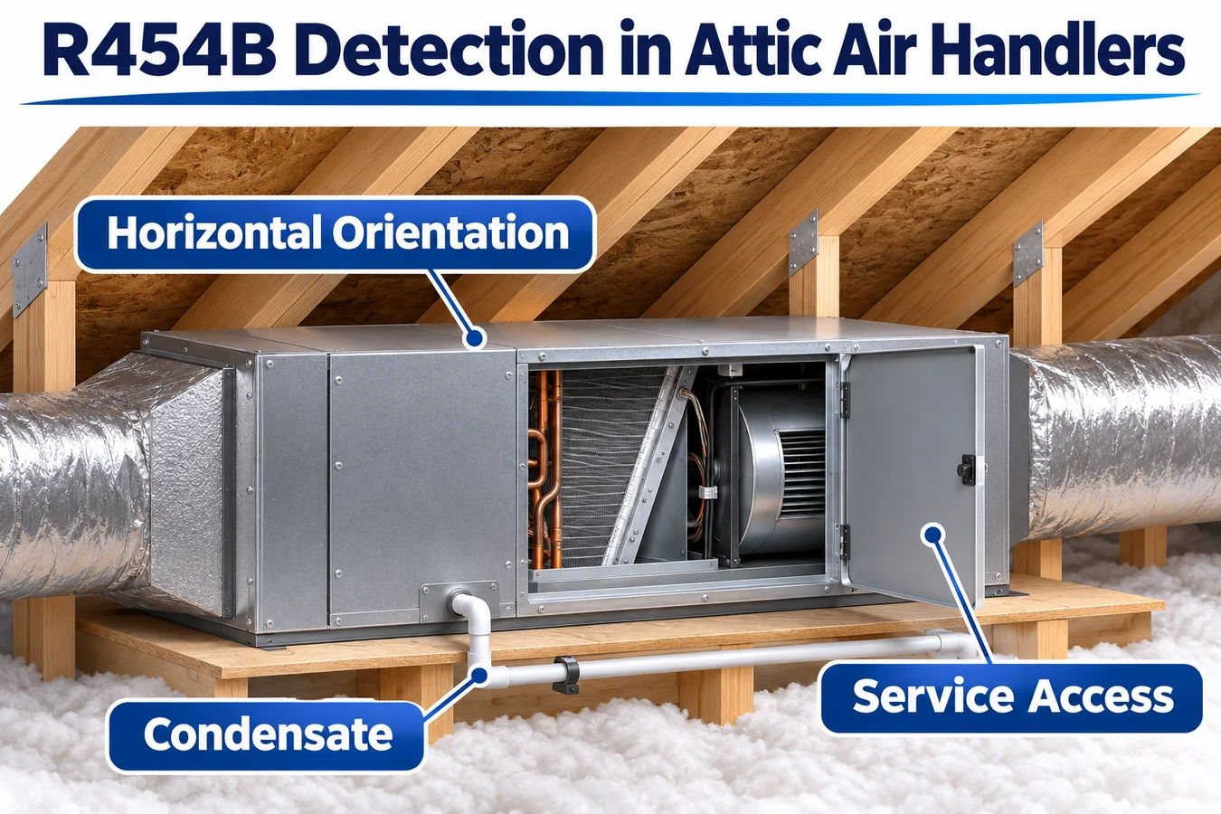
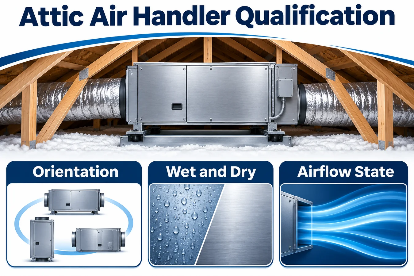
For an OEM developing an R454B sensor for an attic air handler, the difficult part is deciding whether a location qualified in a closed laboratory cabinet still works with the actual horizontal conversion, overhead installation and duct connections. The nominal sensor coordinates may be identical while the release path changes around a relocated pan, a compressed liner or a field fitted return transition. Even a reversible bracket can put its inlet behind a lip when the blower is on the opposite end of the coil.
Start with one installation drawing per released orientation and identify the routes that compete with the detector for refrigerant from each credible release point. Verify the wet and dry routes, the local detector environment and the service conditions that restore the assembly after maintenance. A module exposed to test gas on a bench and a completed appliance carrying refrigerant to that module answer separate questions.
Define the attic installation as part of the equipment boundary
Draw a boundary through the cabinet, its sealed or connected compartments, the return and supply transitions, the condensate connections and the nearby attic volume. Mark the cabinet surfaces that actually separate these spaces. In an attic model, a secondary pan may be immediately below the cabinet while the surrounding attic air is thermally and pneumatically different from the air inside. A return plenum may connect to a different part of the building than the space directly below the unit. Each boundary is useful when investigating where refrigerant went during a test.
For this article, assume a ducted residential split system with an indoor evaporator, a field connected outdoor unit and separate horizontal-left and horizontal-right options. Assume the air handler is suspended or supported above an auxiliary pan and that the manufacturer specifies an integral refrigerant detection system for the example. These assumptions define the engineering case. Identify your own cabinet sizes, coil families, permitted supports, approved accessories, connected equipment and any restrictions on attic installation before adopting the worksheet.
Product markings and model-specific installation instructions establish the installed arrangement. UL Solutions describes an integral detection system as part of the HVAC equipment evaluation and explains why a factory-installed sensor may need to be repositioned when the cabinet orientation changes. UL Solutions guidance on inspecting refrigerant detection systems
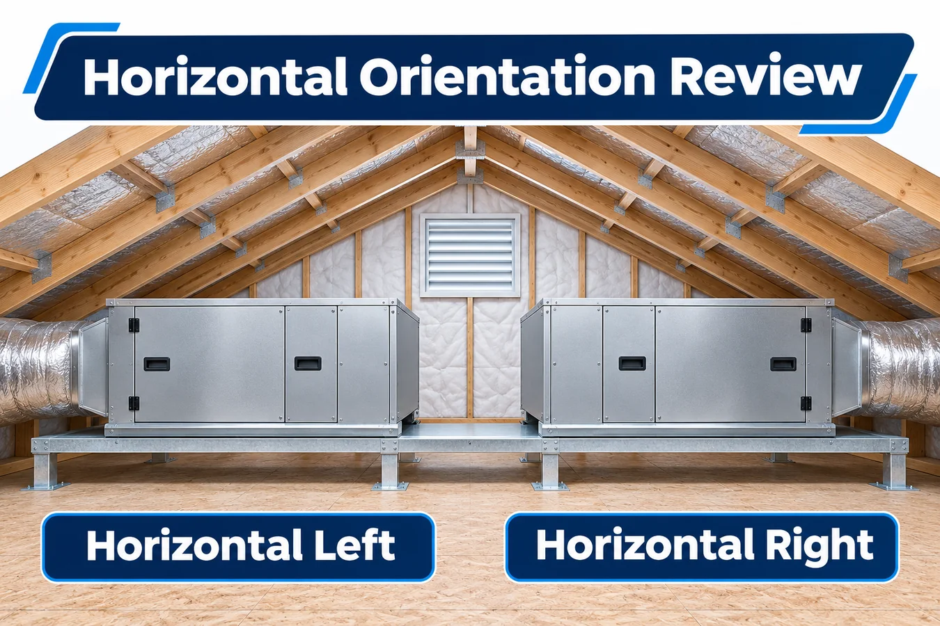
Translate horizontal left and right into drawings with fixed landmarks
Use the manufacturer’s definition of horizontal left and right. In an internal drawing, tie both names to physical landmarks such as the return opening, discharge opening, refrigerant line panel and accessible service face. A technician looking from the attic access side and a designer looking at a factory elevation can call the same side left while facing opposite directions. Draw gravity explicitly on the side and end views. Show the sensing inlet orientation independently of connector orientation.
For each variant, call out the coil, primary pan, supports, drip shields, blanking panels, unused drain ports, bracket and harness retainer. Mark access doors as installed in the view used for the final inspection. A photograph taken with the coil withdrawn can help assembly training, but the released drawing should identify where the inlet ends up with the coil seated and the doors latched. For mirrored metalwork, measure the distance from the inlet to the nearest lip in each actual assembly.
One manufacturer example illustrates why the bracket decision is configuration-specific. ADP’s B Series instructions distinguish slant coils and A-coils and show orientation-specific positions, including a separate multi-position bracket for applicable A-coil horizontal arrangements. That example can inform the structure of an OEM’s review. The appropriate physical arrangement comes from the instructions for the actual unit and configuration. ADP B Series A2L installation instructions
Start the placement study at the leak source
List the indoor circuit features relevant to the equipment evaluation. Use the coil header, distributor, return bends and factory or field joints as initial mapping landmarks where they are present. Treat a release on the line entry side and one behind the coil as distinct test hypotheses even if both feed the same nominal cabinet volume. At each point, draw the direct path, the first surface a jet may hit and the low spaces into which gas can travel when the initial momentum decays.
Consider how the geometry changes the same event. A release can strike a coil shield and move toward a corner instead of continuing along the line of the opening. A pan may collect condensate across its whole footprint while a raised rib divides the adjacent gas space. A harness bundle can leave a small but consequential opening behind a panel. These are hypotheses to instrument. The drawing should give the test team coordinates for the source and for probes that can confirm the routes.
Identify the accessible duct, cabinet and attic measurement points before fixture construction. A synchronized probe in a pocket adjacent to the pan can show early arrival there. An additional probe at the sensing inlet can then distinguish slow transport into the inlet from a slow detector decision after exposure. Keep probes and their holders clear of the flow paths being compared. If the measurement hardware changes an opening or the volume of a small pocket, record the effect or repeat with a less intrusive fixture.
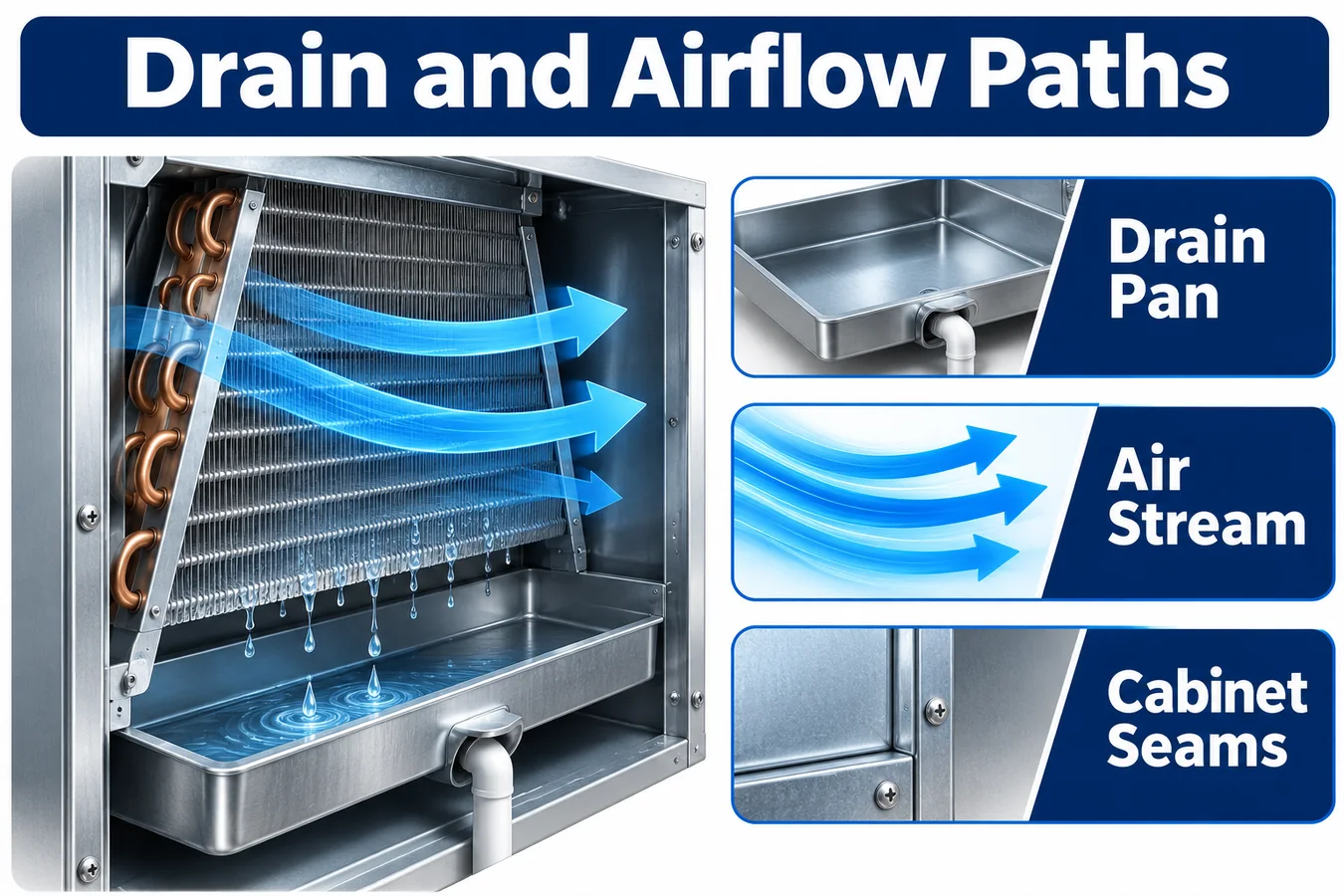
Treat condensate drainage as a gas transport variable
The primary pan directs condensate to a designed outlet. Its slope, ribs, edge heights, covers and drain connection also define local gas paths. A field installed auxiliary pan can sit close to cabinet seams and constrain the air space below them. Show the two pans separately on the drawing and record their actual offsets. A mounting clearance dimension alone cannot reveal which seam opens into a shallow trapped region, especially if the unit has adjustable supports.
Compare normal wet and dry operating conditions. The wet coil and pan can expose the detector area to droplets, wet films and recurring humidity changes. Record whether a drain trap is filled in each run and document the installed drain geometry. A dry trap, a filled trap and a partly obstructed drain can change the available paths. Include conditions associated with normal equipment use and separately identify abnormal conditions evaluated under the qualification plan. Record the state of the secondary pan and any drain switch so the result can be interpreted against the appliance configuration.
If the leading detector location requires a splash shield, test the released shield and bracket together. A shield changes the sensing inlet’s view of the surrounding air. Two shields can direct water equally well while presenting very different openings for gas. If a drain switch or hose is an approved option, compare its footprint against the inlet clearance volume and verify that normal service movement does not move it into that space.
Compare fan states with the cabinet closed
Use closed doors, installed filters and representative duct resistance. Separate the initial condition from any response the equipment initiates after recognition. At the beginning of a test, the fan might be off between calls, operating under cooling demand or running in a continuous ventilation mode. Each condition changes the pressure at gaps and the mixing at the inlet. Evaluate transitions when they are relevant. A release during blower rundown can follow a different route from a release that begins during stable operation.
A location sheltered from high velocity can give useful local exposure with the fan running and collect very little during a quiet period. A point with quick detection at rest can become a bypassed pocket when the blower draws gas along a different corridor. For each hypothesis record when gas reaches the probe near the source, the inlet and the competing route. Record when the controller recognizes the detector state. The order helps the engineering team decide whether to adjust mechanical exposure, review the detector interface or investigate system execution.
Cabinet pressure needs a reference. Measure against the adjoining return, supply or attic volume appropriate to the question. For example, if a suspected opening connects the coil compartment to the attic, a pressure reading relative to the return duct leaves that particular pressure difference unresolved. Log the blower command and the observed operating state on the same time base. If the blower changes state during a run, preserve the original and subsequent parts of the trace.
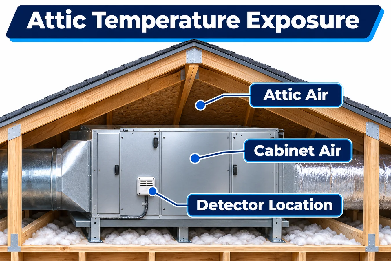
Measure the enclosure temperature at the detector
An attic air temperature reading leaves the sensor microclimate uncertain. During an off cycle, roof and ceiling surfaces can affect the cabinet by radiant heating while the equipment interior gradually warms. During cooling, local air at the detector may be close to a chilled panel or may be isolated from the cooled flow by a partition. A bracket tied to a hot cabinet surface can impose a different thermal condition from one mounted on an internal support. The sensing inlet, electronics enclosure and mounting point can each see different exposures.
Place environmental instrumentation where it can describe those differences. Record attic air at the unit, inlet air, the attachment surface and the detector housing as practical. Correlate temperature and humidity with the duration of the soak, operating state and wetness near the inlet. A summer test can include shutdown soak followed by restart, while a damp start can examine whether local condensation forms when cold internal surfaces meet humid air. Qualify the exposure at the location using the module supplier’s stated conditions and the applicable equipment program.
An approved heat kit, cabinet liner revision or metal bracket substitution can move the detector out of the observed temperature envelope. Carry the environmental instrumentation drawing into change control so a later team knows what was actually measured. UL Solutions identifies temperature and humidity as distinct aspects of the refrigerant detection system evaluation it describes. The specific edition, documents and test conditions belong in the appliance’s compliance plan. UL Solutions overview of updated refrigerant detection system requirements
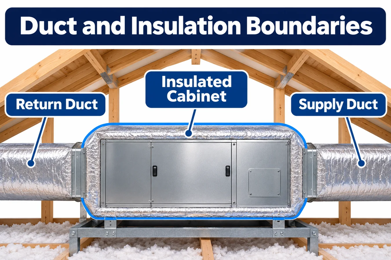
Qualify the duct and insulation interfaces as installed
At the return and supply collars, draw the mechanical overlap from the actual installed cross section. Show fastener penetration, panel flange depth, liner edge, sealant or gasket envelope and any approved adapter. A protruding liner can cover a gap that carried refrigerant into a detection pocket on an unlined prototype. A deep transition may also change pressure near a cabinet seam. Document the installed dimensions of the reference setup, especially when a fabricated shop transition substitutes for a production accessory.
Follow the approved return and supply configuration options through the drawing. Determine which approved transition creates the narrowest local inlet clearance, which creates the lowest pressure at an adjacent opening and which allows the quickest route from the hypothesized source into the duct. These can be three different options. Group configurations only after identifying a physical reason to expect equivalent transport or after comparison confirms it. When uncertain, carry both options into the first test matrix and remove redundant runs based on evidence.
The cabinet insulation must also survive handling. Record any approved adhesive, seams and allowable edge position near the sensor. Check an assembly after environmental conditioning for liner movement, contact with the detector and signs of water held between the liner and bracket. A pullback drawing dimension should identify a durable sheet-metal feature as a datum so a technician can distinguish an intentional opening from a missing piece of insulation.
Make the assembly inspectable from the available service side
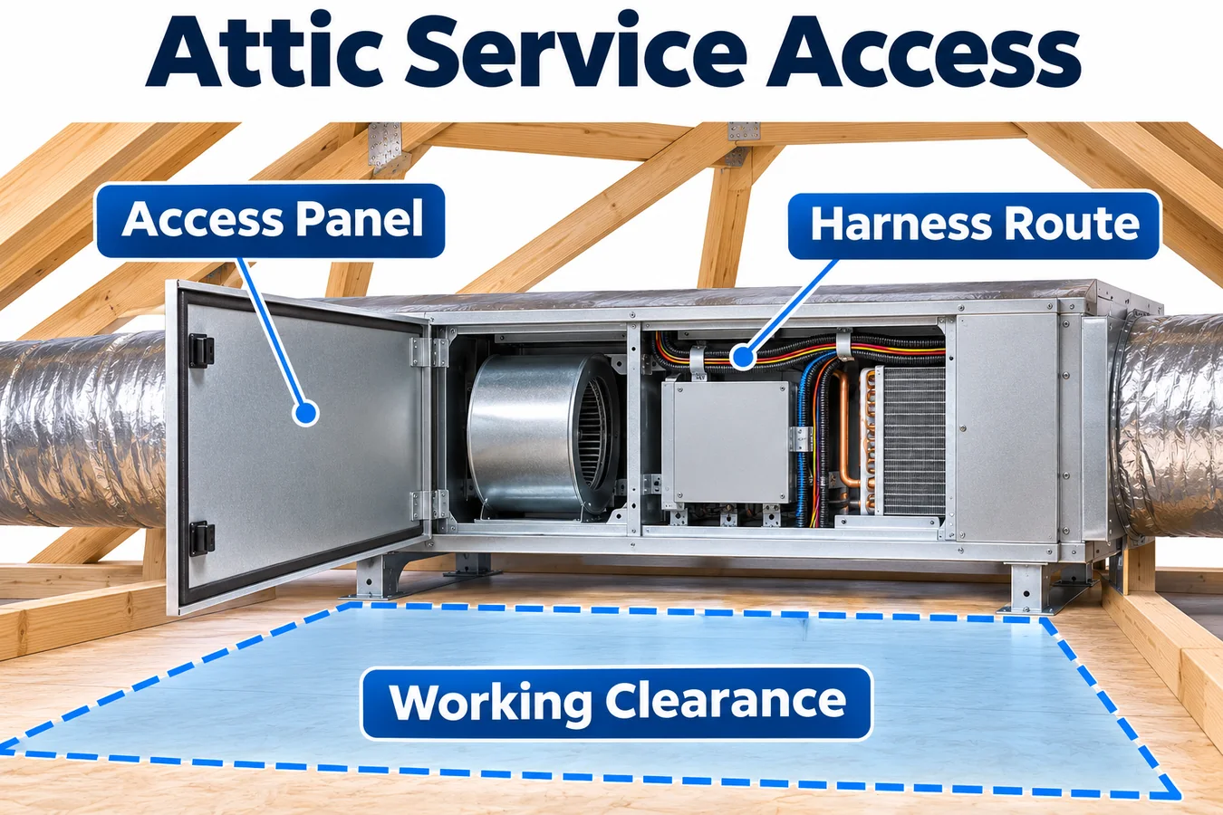
A locator may be visible on a bench while the attic platform, joists or adjacent ductwork conceal it after installation. Have a service representative perform the prescribed inspection on a representative overhead mock-up. Record the view available from the intended working surface, how the sensor part identifier can be read and whether the harness seating and bracket engagement can be confirmed after the coil and pan are in place. If an endoscope or mirror is necessary, establish how the result will be recognized consistently.
Trace the harness through each released route, including the slack used when a cover is removed. Verify clearance from the pan edge, movable coil and door fasteners in both orientations. Locate strain relief so closing the panel cannot tug the connector or rotate the bracket. Mark the locator, connector position and retention features in one illustration where possible. A witness mark on the retaining feature can make an installation mistake easier to identify if it remains visible after reassembly.
Plan the service sequence around what actually moves during cleaning or approved component replacement. If removing the pan also frees the detector bracket, establish how the bracket position is restored and checked. Where moving the coil is involved, verify the resulting harness route with the coil fully seated. Treat the final assembled condition as the acceptance state. A check while the door is open gives service evidence about seating or routing, while the commissioned configuration is the one covered by the qualification.
Rank test cases by the question each one answers
The matrix below is an illustrative starting point. It assumes the same detector configuration can be evaluated in both directions, subject to supplier and appliance evidence. The example rows prioritize competing flow routes and the conditions that could obscure them. Use the released variants and your equipment program to choose actual cases and acceptance criteria.
| Case | Configuration and challenge | Compare these observations | Decision the comparison supports |
|---|---|---|---|
| Left at rest | Closed cabinet, dry drain arrangement, source behind the coil | Arrival near source, pan pocket, inlet and return transition | Whether the proposed bracket faces the collecting space |
| Right at rest | Right conversion with its production shield and a mirrored source landmark | Arrival at corresponding points and measured inlet clearance | Whether the conversion needs independent placement evidence |
| Cooling after soak | Wet coil and normal condensate drainage, restart after warm enclosure soak | Inlet temperature, local condensation, detector output and duct measurements | Whether cooling transient or wetness changes exposure or availability |
| Continuous airflow | Approved blower setting and return transition that draws strongly near a seam | Compartment pressure, inlet trace, bypass route and controller event | Whether the sensor lies in the dominant route at that operating condition |
| Accessory combination | Auxiliary pan, insulated transition and compatible drain accessory at production fit | Inlet clearance, lower seam path and repeatability across builds | Whether accessory compatibility requires explicit mechanical limits |
| Post-service reassembly | Approved service intervention followed by closed cabinet operation | Bracket position, harness seating, detector status and representative exposure test | Whether the service check reliably restores the qualified arrangement |
Where runs disagree, annotate each build with measured geometry, conditioning, leakage of the test fixture and actual starting state. A left-to-right delta can be attributed to cabinet geometry only after accounting for probe relocation, specimen history and airflow. Change one uncertain factor first when isolating a difference. Retain an overall appliance trial in the matrix because single-factor tests can miss a combination that puts the hardware outside the conditions seen during development.
Separate transport evidence from detector and controller evidence
For each run capture the release reference, nearby concentration measurements from the laboratory setup, detector output or diagnostic state, controller recognition and any equipment response observations in a synchronized trace. Label the units and time source. Preserve raw channels when the reporting system averages data. Averaging can obscure the event order that is needed to distinguish a short exposure peak from a persistent channel problem or a blocked transport path.
Illustratively, a return probe might respond before the inlet probe in one orientation. That alone says little about a sensor component. Examine the bracket and local pressure path first. If the inlet probe instead shows exposure and the module gives an unexpected state, investigate local environment, sensor configuration or output handling. If the module indicates the expected event and the equipment controller sees it late, examine the electrical or software boundary. These distinctions keep mechanical changes from masking integration defects.
Add a run sheet that records instrument verification, specimen identifiers, source setup, initial fan state, installed accessories and any uncertainty in aligning clocks. Use the approved laboratory procedures for exposure and the acceptance criteria in the equipment program. An engineering visualization or simulation can help choose locations to instrument. Correlation with appliance measurements is the evidence that lets the program use it to justify a decision.
Hand off a drawing that controls the failure-prone dimensions
Mark the inlet direction, permissible mounting feature, clear volume around the opening, cable route, specified panel configuration and support references as controlled dimensions or features. Include a concise orientation table showing the approved coil, pan, bracket and shield combinations. Include instructions for identifying the drawing revision against the model identifier so a service technician can retrieve the correct arrangement without relying on a family resemblance.
Tie these mechanical features to change triggers. An alternate molding for a drain pan may have the same drain connection while adding a taller reinforcement rib near the inlet. An insulation supplier can produce the same nominal thermal performance with a different cut edge or backing. A duct accessory vendor can maintain flange dimensions while adding an inward stiffener. Review such changes for their ability to alter the gas route and use targeted qualification evidence where appropriate.
Keep an evidence index with each supporting trial, affected configuration and unresolved issue. A planned test with no recorded result belongs in the open work column. A qualification run should identify the exact article tested. Those details let purchasing, manufacturing and service teams trace which production changes can use existing evidence and which require engineering review.
Include one tolerance check that the factory can perform without exposure equipment. For example, locate an inspection gauge from the installed bracket datum and use it to verify the opening left by the pan edge and the liner. Establish the gauge limits from the mechanical envelope represented in qualification. Provide a photo of a correctly seated bracket alongside examples of the relevant assembly mistakes, such as a clip seated in the adjacent slot or a harness retained on the wrong side of the shield. If a check fails, record which feature exceeded the drawing limit and quarantine that configuration until the assembly is reviewed. Periodic inspection of an accepted sample can then show whether the production process continues to preserve the tested geometry.
Candidate module for an OEM evaluation

Winsen lists the ZRT512E R454B and R32 series as a refrigerant detection module family. The ZRT512E-R454B is a candidate for the engineering evaluation described here. Ask for the exact ordering suffix, mechanical drawing, interface definition and environmental documentation for the configuration intended for the R454B appliance. Use those controlled documents to check the housing and inlet geometry, connection details, status handling and the conditions used in qualification. Winsen ZRT512E series product documentation
Frequently asked questions
Can one bracket be used in both horizontal orientations? A common part can be viable when its installed position and inlet clearance meet the design intent in each assembly. Locate the bracket with respect to the actual pan and coil in both views. Compare appliance exposure for the relevant source and fan cases and link the results to the two part configurations.
Does an auxiliary pan always change the detector location? Its effect depends on the cabinet openings, the gap beneath the cabinet and the permitted mounting arrangement. First identify paths the auxiliary pan could constrain. A comparison with production clearances can then show whether the pan belongs in the configuration evidence or whether a mechanical condition needs to be controlled.
Can an off-cycle result cover a continuously running blower? Use each result for the airflow state it represents unless the test plan establishes a defensible basis for broader coverage. Fan operation can change both the route and the dilution near the sensing inlet. Review relevant fan transitions where the installed controls make those transitions possible.
Which temperature belongs on the sensor comparison sheet? Record the environmental quantities specified in the supplier’s controlled documentation and the corresponding measured quantities at the proposed mounting position. Include the operating state, sensor location, soak condition and wetness observations. Attic ambient remains useful as boundary information and for reproducing the test.
What is the most useful drawing for service? Use the view from the prescribed access side, with both the physical assembly landmark and the inlet shown. Include the final pan position, intended connector and harness retention. Provide separate views when changing orientation changes what can be seen with the unit installed.
Request an OEM configuration review
Send the two horizontal orientation drawings, approved coil and pan combinations, intended attic support and duct transitions, field accessory list and current detector interface requirements. Include a service-side photo or mock-up and any inlet temperature or gas transport traces already available. Indicate which configurations are proposed, which are released and which still need evidence. With those inputs, an OEM review can produce a candidate location list, a mechanical and electrical interface checklist and a qualification matrix tied to the actual appliance variants.
Review the ZRT512E product listing ಮತ್ತು submit the equipment details for an OEM integration review.
