
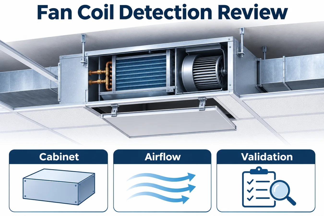
An R454B sensor fan coil project starts with the unit that will actually be installed. A shallow concealed cabinet, a return plenum, an optional filter box and a ceiling access opening can each affect detection or service. The equipment team needs a defined relationship between a credible refrigerant release, gas arrival at the detector, valid controller input and the physical equipment response.
This guide assumes an illustrative ducted indoor unit with a coil, motorized blower, condensate pan and connected outdoor equipment. Examples describe engineering decisions and evidence to request. The exact appliance requirements, installation instructions and certification program determine the released detection and mitigation function. UL Solutions describes an integral refrigerant detection system as stationary sensing coupled to automatic mitigation and explains its evaluation within the appliance. Az UL Solutions integrált RDS-útmutatója
Define which fan coil configurations the evidence covers
Create a configuration ledger before comparing detectors. Record cabinet size, coil construction, pan revision, blower assembly, inlet and outlet arrangement, controls, refrigerant identity and approved mounting orientations. Add optional return boxes, pumps, heaters and field conversion kits when they change an air path, electrical dependency or service route. Assign each buildable arrangement a stable identifier connected to the bill of materials.
A concealed duct family may use one electronics platform across several cabinet depths. That common board can simplify interface development while the mechanical variants still require separate transport review. A side connection compartment may also move between sizes. Identify the characteristics that justify shared evidence and the differences that require more work. The ledger should make an omitted arrangement visible before the marketing model expands.
Separate appliance options from surrounding installation conditions. The OEM may define a permitted duct resistance envelope while the actual duct layout is supplied by others. State the boundary conditions represented in the tests, which instructions establish them and how their applicability is checked. Include the maximum relevant refrigerant inventory for the approved equipment combinations in the program’s controlled requirements, without turning an illustrative article into a charge prescription.
Give every row an owner and an evidence status. An open row should point to a missing trial, an unresolved interface meaning or a drawing awaiting release. A reviewer can then decide whether a proposed shipment is covered, rather than inferring approval from a shared cabinet name.
Map the concealed cabinet and connected air path
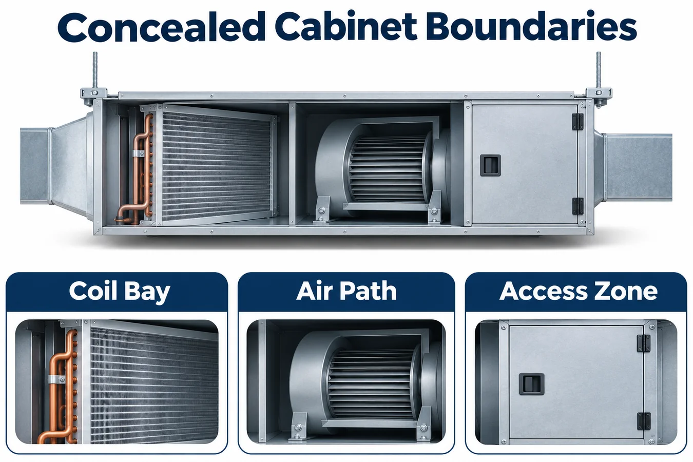
Draw sections through the coil bay, fan compartment, electrical area and connections. Show the installed gravity direction independently from the normal airflow direction. Include pan edges, insulation joints, tube openings, harness passages, removable covers and drain connections. For a concealed installation, draw the approved return and supply interfaces and the access envelope around the cabinet.
Use the drawing to ask where gas can travel with the fan idle and how operation changes that route. An insulation strip can partition a pocket even when the exterior cabinet is continuous. A negative pressure compartment may draw air through a seam, while a neighboring positive pressure region releases air through another opening. The specific construction and operating condition establish which mechanism matters.
Distinguish the equipment air path from the surrounding ceiling void. If the design relies on containment or exchange across a boundary, identify the controlled construction that supports that assumption. A removable service cover may have different leakage after repeated access. A field return box can introduce a new seam or pocket. Bring those features into the evidence plan wherever they affect the claimed detection function.
Keep candidate sensing locations as engineering hypotheses until representative trials establish coverage. An accessible surface can be attractive for service and still have weak exposure to a release behind a pan divider. A position with good inlet exposure must also remain compatible with moisture, temperature and mounting requirements.
Build release cases from the refrigerant construction
Assign source identifiers to relevant coil headers, distributor regions, feeder joints, return bends and connection areas within the assessed boundary. Describe each source’s relationship to cabinet partitions and the airflow field. Group cases only when their transport mechanism is credibly equivalent. Geometric proximity alone may conceal a dividing flange or a route into another compartment.
For an illustrative narrow cabinet, assume the coil connection area lies beside a pan lip. With the blower idle, a release from the connection region first enters the side volume. During blower operation, that volume exchanges with a faster moving stream near the slab edge. The test plan should address the idle pocket and the operating transport path, including the transition between them if its mechanism differs from either steady case.
Record the reasoning behind the representative release point. A fixture tube that points directly at the detector may create a path that the actual joint does not provide. Reference the installed source geometry, document fixture intrusion and keep reference measurement positions stable. Where the protocol uses a surrogate arrangement for preliminary work, identify which conclusions still require representative equipment trials.
Trace every release case back to the drawing. When a joint moves, a coil revision adds a cover or a connection kit changes its enclosure, the team can identify the affected cases. The release map becomes a practical change review tool rather than a picture filed beside the test report.
Cover fan states and transitions explicitly
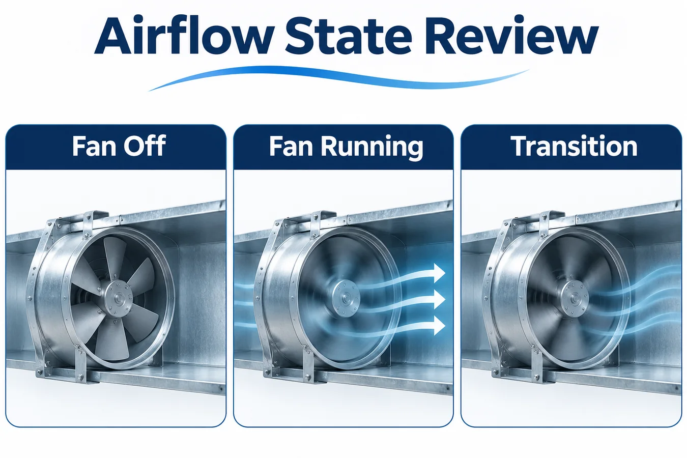
Build the operating map around actual blower behavior. Include relevant idle, low flow, normal demand, shutdown and mitigation states, as well as transitions that change the transport route. Record the requested mode and the observed equipment condition separately. A command can be present while the motor ramps or a receiving board delays action.
Select trials across the approved external resistance range using the mechanism being challenged. A low flow condition may create a long residence time in a cabinet pocket. Higher flow may dilute inlet exposure or redirect gas. A fan start can clear an idle collection zone before another sensing region receives the release. The useful comparison connects the observed inlet exposure with the operating condition.
In a variable speed platform, log the actual control mode and any automatic adaptation that changes airflow. If an accessory controller or building command can select a mode, establish how the mitigation request interacts with that authority. A test at one nominal setting does not establish priority across all available modes.
Avoid treating blower feedback as complete evidence of gas transport. The motor can achieve its requested state while cabinet geometry still routes a release away from the inlet. Transport evidence and actuator evidence meet in the installed system test, with each measurement explaining a different part of the chain.
Review condensate exposure and service access together
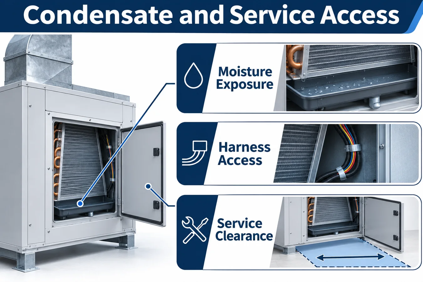
Review wet operation with the same cabinet and pan parts intended for production. Identify ordinary condensate routes, splash or carryover mechanisms relevant to the unit and the exposure at a candidate detector and connector. Compare those conditions with the exact detector configuration’s environmental documentation. Include startup after an extended wet or idle condition where the equipment program identifies it as relevant.
Document the bracket and inlet orientation using controlled datums. A generic instruction to keep the sensor dry does not define an assembly. Record the allowed mounting construction, tolerances and access for inspection. Evaluate any cover or shield as part of the sensing path because a feature introduced for moisture protection can also alter gas exchange.
For concealed equipment, simulate service through the intended access opening. Determine whether a technician can identify the part, release the connector and restore the bracket without removing unrelated ductwork or changing the inlet orientation. Check the action with the cabinet in its installed orientation and with ordinary obstructions represented.
If the unit needs a particular access envelope, connect the mechanical drawing to the installation documentation. Serviceability affects whether the validated construction can be restored after replacement. The review should identify observable features a technician can compare with the released illustration, including connector retention and harness clearance when panels close.
Assign control authority across the indoor and outdoor equipment
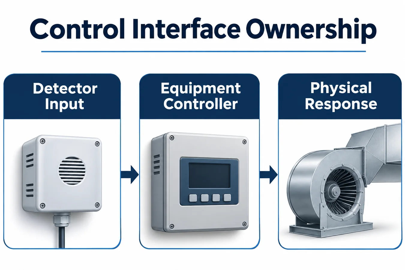
Define who validates the detector input, who decides the mitigation state and who owns each physical output. An indoor board may command the blower while an outdoor controller owns compressor permission. A building interface may carry a demand or status indication without having authority to release a retained event. Write these distinctions into the interface specification.
For every connection, state the asserted meaning, validity conditions, startup behavior and unavailable-input policy. If a digital report carries concentration and status, establish which fields make the observation eligible. If a discrete level is used, document the electrical and power assumptions needed to interpret each level. Review the exact board and firmware at the receiving end.
Illustrate one interrupted sequence. Assume the indoor controller accepts an event, sends the approved request to the outdoor board and then restarts. Determine what the outdoor board observes while the indoor software initializes, what information is retained and which observations must be acquired again. Use measurements at the actual equipment interfaces to establish the physical behavior.
A building command or ordinary thermostat request can arrive during that sequence. The released output arbitration must define its effect while restrictions are active. Keep a single accountable policy for the outputs so a comfort control task cannot overwrite a mitigation command on its next update.
Distinguish commands, acknowledgments and physical proof
Draw the detection and response timeline using identifiable landmarks. Include gas arrival near the inlet, eligible detector output, controller acceptance, output request, receiving-board response and the physical outcome used by the equipment program. The intervals help the lab distinguish transport delay from signal handling or actuator behavior.
An acknowledgment establishes the meaning defined by its interface contract. It may confirm that a message arrived without proving the requested airflow. Select evidence that supports the actual acceptance criterion. Where direct measurement is required in qualification, record the instrument, location and operating condition used to characterize the response.
Define how existing operation affects proof. If the fan is already running when an event arrives, determine whether its current status qualifies for the required mitigation operating condition. A status sample captured before the mode change can require freshness or mode information before the supervisor uses it. The decision should be explicit in the test protocol.
Include a trial where the command is accepted but the intended physical response is unavailable. Observe the equipment’s defined restricted behavior and retained state. A trace containing a command alone cannot close a requirement about an actuator outcome. Give partial evidence its own disposition so incomplete measurements remain visible.
Use a configuration and evidence matrix
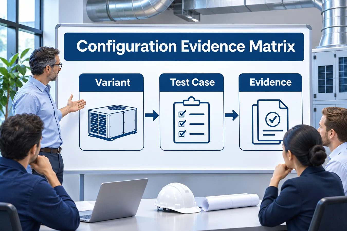
The following example uses fictional variants of a concealed duct fan coil. It illustrates how a team can organize decisions while the actual acceptance criteria stay in the controlled equipment requirements.
| Variant | Changed feature | Engineering question | Evidence to close |
|---|---|---|---|
| Shallow cabinet baseline | Standard pan and direct return | Do selected sources reach the inlet across the offered fan modes? | Representative transport and response trials |
| Return box option | Added enclosure and seam | Does the option introduce a collection or exchange route? | Geometry comparison and affected release cases |
| Pump option | Different service parts and power dependency | Can installation and replacement preserve the validated assembly? | Wet exposure review, power analysis and access trial |
| Alternate blower | Different motor and control program | Does the transition or available airflow change? | Fan characterization and repeated affected cases |
| Remote controls option | Changed request and status path | Is output authority maintained through link interruption? | Interface and restart evidence |
Give each row drawing, firmware and evidence identifiers. Capture why an inherited result applies and which physical or electrical characteristic would invalidate that inheritance. A simple “same as baseline” entry leaves the next engineer without a basis for judging a component change.
Use the matrix to select meaningful trials. It can reduce repetition when evidence supports equivalence while preserving dedicated trials for different mechanisms. The reviewer should be able to see which rows are released, which remain open and what concrete work is needed to change their status.
Plan installed testing in layers
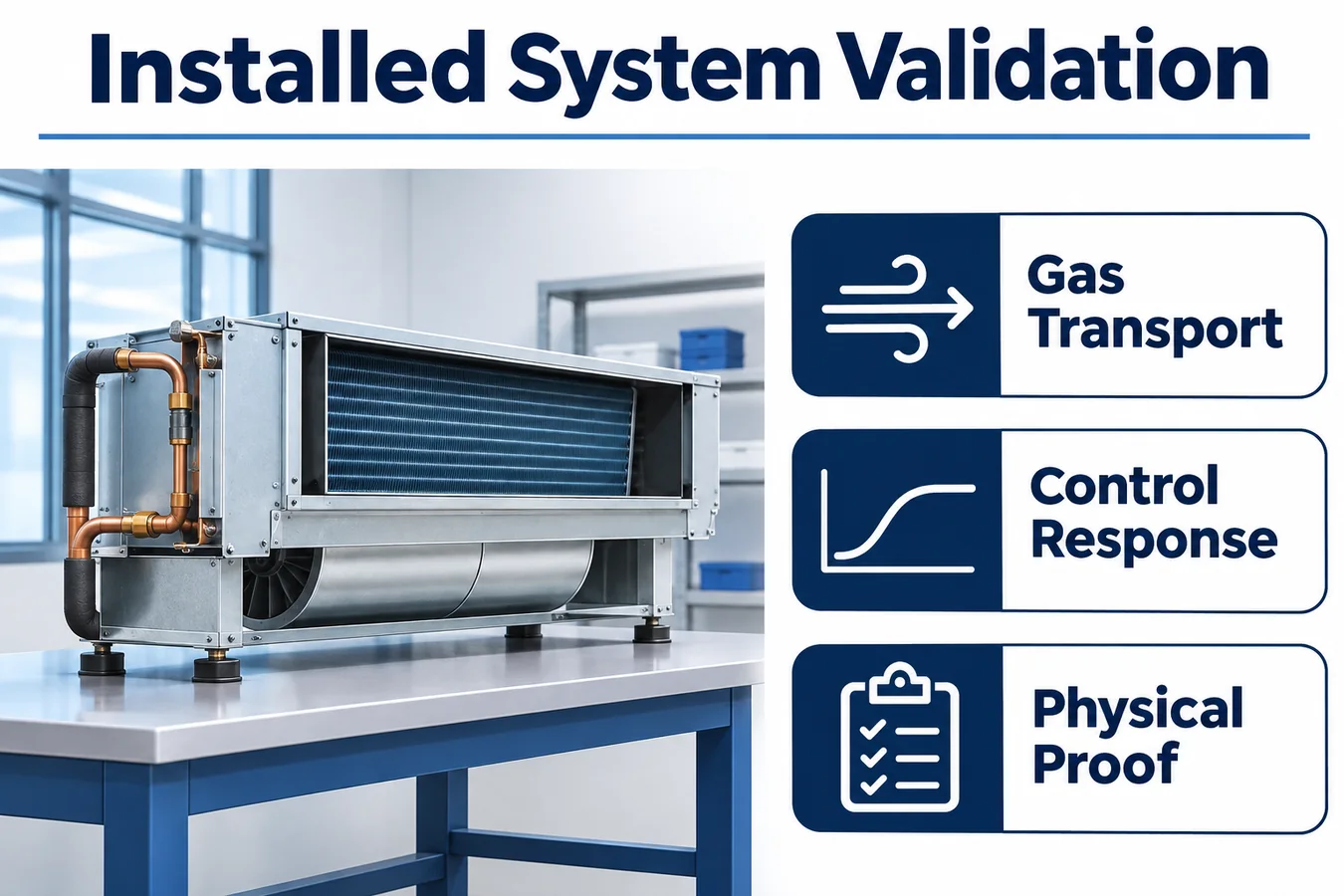
Begin with controlled fixture work to understand inlet exposure and detector behavior. Move to representative cabinets to evaluate release paths, then exercise the assembled equipment with its actual controller and actuators. Maintain common identifiers across these stages so an observation in a fixture is not mistaken for an installed result.
Record cabinet and pan revisions, panel state, filter and return arrangement, blower configuration, interface revision and detector sample identity. Include photographs that locate the reference instruments and source fixture against cabinet datums. These details allow the lab to reproduce a disputed trace or identify which later variant needs additional work.
Set rules for missing or unusable data before trials begin. A shifted reference instrument, an interrupted controller log or an unrecorded fan mode can limit what a run establishes. Keep the trace for diagnosis, assign its evidence status and repeat the affected acceptance work where needed. This protects the matrix from closing a requirement that was never observed.
After the installed sequence is established, challenge power and signal dependencies. Test the relevant detector, decision-board and actuator-board restart combinations, including the case where only one board loses power. Inspect the actual outputs during boot and the point where current status becomes eligible again. The physical chain includes the intervals before application software resumes.
Work through a concealed unit example
Assume the baseline cabinet is released with a particular pan, blower program and return arrangement. A product change adds a return box to simplify installation. The enclosure attaches to an existing flange and leaves the sensor assembly untouched. The change request claims the detector and controller tests can be inherited.
The reviewer first compares the transport drawing. The new box introduces a volume beside the connection compartment and changes a seam that exchanged with the surrounding space. The affected source cases are identified from the release map. The team chooses comparison trials with the fan idle, at a relevant low flow condition and during the transition that changes exchange at the seam.
Next, the reviewer compares the electrical arrangement. If detector power, harness and controller remain equivalent, existing interface evidence may remain applicable, subject to the documented review. If the option also moves the control enclosure to improve access, harness routing and disturbance exposure enter the scope even though the schematic appears unchanged.
The final disposition separates evidence by mechanism. Transport trials close the added volume and seam questions. A service mock-up confirms that the access opening permits restoration of the intended assembly. Applicable electrical evidence is referenced with its inheritance basis. The row is released only after each identified question has a disposition and the drawings describe the tested construction.
Compare service access with gas exposure on the installed cabinet
Consider a shallow cabinet offered with either a full-width return opening or a side-entry return box. Both versions use the same coil and control board. The full-width version has an access panel under the coil bay, while the side-entry version has an additional divider and a smaller opening for reaching the sensor. A candidate position behind that opening makes replacement straightforward, but the divider may change how refrigerant from a connection bay reaches the sensing opening. The drawing and airflow study should account for both the divider and the production service panel.
Start the comparison by writing down what each design is intended to improve. A detector near the access opening can be easier to identify and replace. A detector closer to the coil bay can shorten the expected transport path for some release sources. The harness on either side may need a different retention or strain relief arrangement. Ask the mechanical team to confirm bracket and connector clearances on the installed unit, including the ceiling access envelope represented in the instructions.
Then use the same release and controller observations to evaluate both options. Compare fan-off, fan-running and relevant transition cases selected by the program. Record detector response and the resulting equipment actions, with the access cover and return box in the released condition. A test performed with a service panel removed may be useful for troubleshooting. Its airflow boundary should be recorded clearly before its evidence is used to support a closed-cabinet construction.
A successful service trial should include identifying the part, reaching the fasteners, reinstalling the approved harness route and confirming that the sensing opening is exposed after closure. Record what the technician could see and what the instruction had to specify. If the return box is installed in the field, link the approved combination to the equipment identification and the box instructions. The release package should make the approved configuration easy to recognize before it is enclosed above a ceiling.
Keep manufacturing and service records connected
Translate the validated assembly into production features that can be inspected. Record the detector and bracket revision, harness identity, connector retention and panel or seal features involved in the evidence. Use a fixture or visual check suited to the characteristic. A part-presence check alone may miss a reversed mount or a trapped service loop.
Maintain exact compatibility information for service. The replacement record should connect the unit model and serial range with the detector configuration, bracket, harness and required restoration checks. If a supersession changes initialization or status behavior, review the receiving firmware and update the service path accordingly. A connector fit establishes only a mechanical fact.
Feed field observations back into the configuration ledger. Useful reports identify the actual unit, option kit, orientation, operating phase and part revisions. A description tied to those details can lead to a repeatable lab case. A generic “alarm problem” report leaves the engineering team guessing which combination and mechanism to investigate.
Define change triggers for renewed review. Pan geometry, insulation, blower programming, return accessories, controller firmware and service parts can affect different portions of the evidence. Identify the affected matrix rows and make the inheritance decision explicit, including the owner who accepts it.
Evaluate the ZRT512E configuration as a candidate

Winsen lists the ZRT512E family for R454B and R32 applications. Treat the exact ZRT512E-R454B configuration as a candidate for the fan coil program. Request the controlled mechanical drawing, gas configuration, interface specification, environmental evidence and revision identification associated with the intended orderable part. Qualification depends on the supplied configuration and its installed integration. Winsen ZRT512E family information
Use the sample review to connect supplier documentation with equipment decisions. Compare the mounting and exposure assumptions with the cabinet concept, then agree the interface behavior needed during startup and interruption. Preserve sample identifiers in the test report so later procurement and production work can trace the evidence. Review the local product information with the controlled supplier package. ZRT512E product candidate
Gyakran ismételt kérdések
Can one concealed unit size represent the whole family?
It can represent the conditions for which the equivalence case is supported. Compare transport geometry, source locations, pan and partition details, fan behavior and interface architecture. Keep separate evidence where a difference changes the mechanism being assessed. Record the boundary of every inheritance decision.
Does a function test prove the mounting location?
A function test can demonstrate defined electrical and actuator behavior. The path from a credible release to the sensing inlet requires transport evidence under representative cabinet and operating conditions. Identify the portion of the chain each method establishes and keep both in the release package.
Should the most accessible mounting surface be selected?
Accessibility belongs in the decision alongside exposure, environment and assembly consistency. Evaluate candidate locations against the release cases and the exact detector’s mounting documentation. A service mock-up then checks whether the validated construction can be identified and restored through the intended access.
Can a building controller release the event?
The equipment requirements define authorization and recovery. Document what the building interface is permitted to request, which component decides eligibility and what happens when the communication path is unavailable. Verify that ordinary commands do not change the defined restrictions during an active or retained event.
Request an OEM fan coil integration review
Prepare cabinet sections, offered orientations, pan and return options, refrigerant source regions, fan operating envelopes and the proposed control contract. Add the configuration matrix and identify which evidence your lab plans to obtain. Ask for the exact candidate documentation and representative samples that match the intended supply and interface.
Use the review to close specific questions about detector exposure, installed environment, interface validity and sample identity. Agree which prototype revisions the first trials will use and how the evidence will connect to the release ledger. Share the equipment context and request an application discussion through the local OEM contact. Vegye fel a kapcsolatot a hűtőközeg-érzékelő csapatával
