

An R32 detector output is only the first event in a refrigerant detection system. The equipment controller must decide when the signal is valid, move the system into the evaluated mitigation state, verify critical commands, manage faults and prevent an unsafe restart. Ambiguous sequencing at this stage can defeat otherwise good sensor placement.
This control guide shows how to translate the equipment safety concept into a deterministic state machine. Exact thresholds, delays, blower behavior, compressor inhibit, heating response and reset rules remain equipment-specific and must follow the certified design and manufacturer instructions.
Start with hazards and required outcomes
Write the expected outcome before writing code. Identify the refrigerant charge, occupied-space assumptions, credible release conditions, airflow paths, ignition sources and functions needed to reduce risk. The result may include inhibiting refrigerant operation, establishing a defined airflow path, providing indication and retaining a service event.
Turn each outcome into a requirement that can be observed. “Stop cooling” should identify the command path and acceptable confirmation time. “Run the blower” should define requested speed or airflow, available feedback and behavior when feedback is absent. Link every requirement to a qualification test.
Document the normal and alarm output maps
Create a table of every output in each state. Include compressor request, reversing-valve logic where applicable, indoor blower, zone dampers, bypass devices, gas heat, fresh-air devices, alarm indication, remote communications and service logging.
| Output or function | Normal state | Confirmed R32 alarm | Design question |
|---|---|---|---|
| Refrigerant operation | demand-controlled | inhibited as specified | how is response confirmed? |
| Indoor blower | comfort sequence | evaluated mitigation state | what feedback proves airflow? |
| Dampers | zone-controlled | specified safe path | what if a damper is unavailable? |
| Gas heat | heat sequence | equipment-specific response | how are ignition and purge handled? |
| Reset | normal transitions | latched or conditional | who authorizes return? |
The table prevents an accessory or secondary mode from remaining in a contradictory state.

Use explicit states instead of scattered alarm flags
A useful architecture separates NORMAL, SUSPECT or DEBOUNCE, CONFIRMED ALARM, MITIGATION, LATCHED, RECOVERY CHECK and RESET. A separate FAULT state or fault overlay handles loss of detection capability. Names can differ, but entry conditions, outputs, timeouts and exits must be explicit.
The suspect state should implement only the conditioning supported by the detector and system specification. Excess filtering can delay mitigation. A confirmed alarm should pre-empt comfort logic at a defined priority. The controller must also define its state after reboot when an alarm or latch was active before power loss.

Distinguish an alarm from a detection-system fault
A gas alarm indicates that the sensing channel met the refrigerant criterion. A fault indicates that the channel, wiring, power or communication may be unable to make a valid decision. Record them separately, display different service information and validate both.
Fault examples include open or short circuits, invalid data, missing heartbeat, frozen value, startup failure and internal diagnostics. Define whether each fault uses the same conservative equipment outputs as an alarm or a different evaluated safe state. Never interpret missing or stale data as “no refrigerant.”
Inhibit refrigerant operation through a verified path
Identify the chain from the indoor safety controller to the outdoor equipment. It may use thermostat conductors, a dedicated inhibit input, relay contacts or a communicating protocol. State the safe electrical level, transition timing, retry policy and communication timeout.
Where feedback exists, verify that the outdoor unit accepted the command and that the compressor or refrigerant-producing function remains inhibited. If feedback is unavailable, validate the architecture’s behavior and diagnostic coverage through equipment tests. Loss of the command path during an alarm needs an explicit state and indication.

Command the blower according to the evaluated design
Many A2L HVAC designs use indoor airflow as part of mitigation, but the required state is not universal. Define the commanded profile, ramp time, minimum duration or condition, allowable interruptions and feedback. Resolve interactions with fan delays, quiet modes, dehumidification and thermostat fan commands.
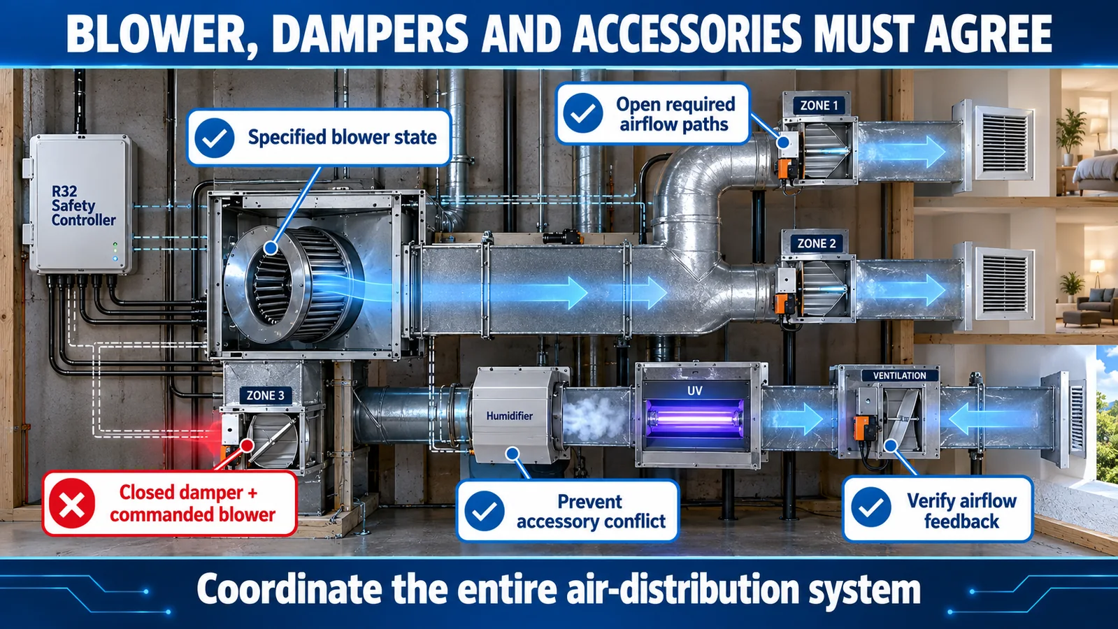
Treat “commanded on” and “airflow available” as different facts. A stalled motor, disconnected feedback, blocked filter or closed damper can prevent the intended air movement. Specify the safe response and service indication when the required airflow cannot be proven.
Coordinate zone dampers and accessories
Zoning can concentrate or restrict airflow if dampers remain under comfort control during an alarm. Define which dampers open, which controller owns them, the transition time and the response to a stuck or offline actuator. Include bypass dampers and pressure-relief logic.
Fresh-air controls, humidifiers, electronic air cleaners and auxiliary fans may also change airflow or introduce electrical states that matter to the evaluated design. Build an interface list for every supported accessory combination rather than relying on an undocumented broadcast alarm.
Treat gas heating as an independent control branch
In a furnace-and-coil system, a refrigerant alarm can occur during a heating call or after cooling has stopped. Decide how the alarm affects ignition, gas valve, inducer, supply-air limits, blower timing and post-purge. An instruction to inhibit the compressor does not by itself define a safe gas-heating response.
Document whether heating continues, shuts down immediately or follows a controlled sequence under the evaluated design. Verify priority when the furnace safety controls, R32 mitigation request and thermostat demand disagree.
Latch the event with defined persistence
A latch prevents short concentration fluctuations, controller reboot or communication recovery from silently restoring normal operation. Specify where the latch is stored, whether it survives power loss, how two controllers synchronize it and what happens after board replacement.
Retain the cause, timestamp or sequence counter, maximum observed value if supported, active faults and commands issued. The user indication should distinguish an active gas condition, a retained alarm and a detection-system fault so service work is directed correctly.
Require evidence before reset
Reset criteria may include a concentration condition, minimum clear time, valid sensor diagnostics, healthy communication, proven blower availability and an authorized automatic, manual or service action. The exact combination is equipment-specific. Elapsed time alone does not show that the sensor, airflow and command paths have recovered.
Define what happens if the signal rises again during recovery or a diagnostic fault appears. Return outputs to normal in a controlled order and preserve the event history even after the active latch clears.

Define communication timeout and power-loss behavior
For every link, set a valid-message interval and a timeout based on the safety requirements, not only network convenience. Specify the output state when indoor-to-outdoor communication fails, when the sensor link fails and when an accessory controller disappears.
Power interruption tests should include brownout, rapid cycling and different restart times for connected boards. Prevent a brief compressor enable while the detector warms up or before a retained latch is restored. If automatic restart is allowed, state all prerequisites and verify them.
Make diagnostics useful to technicians
Expose the state that caused the response: gas alarm, sensor fault, communication timeout, blower feedback failure or outdoor inhibit failure. Use fault codes that map to service documentation. Record commanded and confirmed states so technicians can locate the failed part of the chain.
Avoid a single generic “R32 fault” for every case. It can cause unnecessary sensor replacement when the real problem is a harness, controller, damper or outdoor communication link. A functional service test should verify the chain without an uncontrolled refrigerant release.
Verify every transition with fault injection
Build a matrix for normal detection, slow signal rise, alarm threshold crossing, sensor disconnect, invalid data, communication timeout, blower feedback failure, outdoor response failure, power interruption and recovery. Record controller state, commands, feedback, indication, event log and final safe state.
Use production-intent firmware, wiring, accessories, filters and airflow restrictions. Repeat boundary cases and confirm deterministic timing. Test combinations, such as a gas alarm followed by loss of blower feedback, because layered failures expose priority and recovery errors that single-fault tests may miss.

Control software changes after qualification
Trace every state, timeout and output requirement to code and test evidence. Use configuration control for detector variant, thresholds, protocol version, blower profile and reset policy. A comfort-feature software update can change the safety sequence if priorities or shared outputs are altered.
Regression tests should run the complete alarm and fault matrix after relevant controller, sensor, motor, damper or communication changes. Review field logs for ambiguous faults and feed confirmed findings back into diagnostics and service instructions.
Match the detector output to the control architecture
Winsen’s ZRT510 R32 refrigerant sensor module is listed in the official WooCommerce export as an NDIR R32 module, with PWM, RS485 and UART in the product attributes. Certification statements and detailed engineering specifications require current controlled evidence; confirm the exact variant, interface behavior, limits, dimensions and qualification documents before selection.

Read the related guides on furnace-and-coil sensor integration, RDS requirements for R32 and R454B equipment, A2L sensor selection and UL 60335-2-40 sensor requirements.
What to send for a control-sequence review
Provide the refrigerant and charge, equipment type, airflow and accessory architecture, sensor output, controller interfaces, alarm target, timing budget, required feedback, fault list, reset concept, environment, annual volume and certification market. Winsen can review detector-interface choices and the validation matrix for the intended equipment.
Contact Winsen for an R32 control-sequence review.
References
- UL Solutions: Inspecting Refrigerant Detection Systems in HVAC Equipment
- UL Solutions: Updated Requirements for Refrigerant Detection Systems
- UL Solutions: Sensor Response in HVAC Systems
- AHRI Flammable Refrigerants Research Initiative
- AHRTI and UL Solutions: Sensor Response Technical Report
- Daikin A2L Refrigerant Detection System Accessory Instructions
