
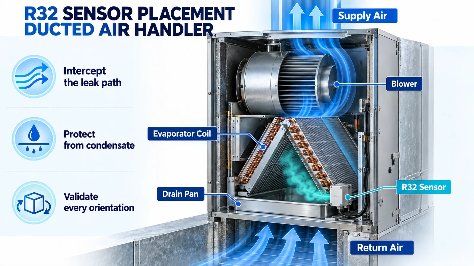
A refrigerant detector in a ducted R32 air handler is part of an equipment-level safety function. Its location therefore cannot be selected from one rule such as “put it low” or “put it beside the coil.” The correct location is the point that detects every credible release quickly enough, remains dry and serviceable, and still works when the blower state or approved cabinet orientation changes.
This guide gives HVAC design engineers a practical placement and validation method. It is intended for product development and qualification. The final position, alarm threshold, controller logic and mitigation sequence must follow the certified equipment design, the applicable standard and the manufacturer’s installation instructions.
Start with the safety function, not the bracket
Define what the refrigerant detection system must accomplish before choosing a mounting surface. For a given air handler, document the refrigerant, maximum charge, cabinet volume, approved orientations, likely release points, sensor interface, alarm or fault outputs, required response time, mitigation action and reset behavior.
An integral detector is evaluated as part of the HVAC equipment. A component with a suitable sensing principle does not by itself prove that the assembled system will respond at the right time. The sensor, harness, controller, fan command and fault diagnostics form one chain. A placement decision is acceptable only when that chain has been tested in the intended equipment.
Map credible leak sources around the indoor coil
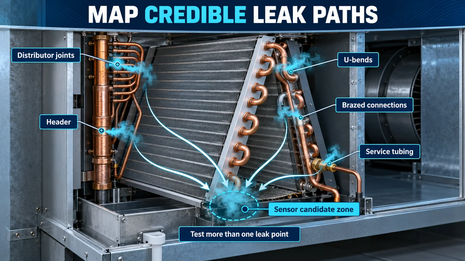
Begin with a marked-up cabinet drawing or physical prototype. Include the distributor, return bends, headers, braze joints, service tubing, valves and connections that are inside the enclosure. Record the direction in which each joint could discharge and the surfaces the jet may strike.
The highest-probability source is not automatically the worst detection case. A small release behind a baffle may reach a detector more slowly than a larger release into the main airstream. A release near the panel seam may escape the cabinet instead of crossing an internal candidate point. Test coverage therefore needs a set of credible sources, including sources on opposite sides of the coil when the circuit geometry allows them.
Trace the plume with the blower off and on
With the blower off, a released R32 cloud has a downward buoyancy tendency because R32 has a higher molecular weight than dry air. However, the initial jet has momentum, entrains surrounding air and may strike the coil, drain pan or cabinet wall. These effects can move the plume laterally before a lower pocket forms.
With the blower on, the concentration field changes again. Return air can transport the release through the coil section, dilute a local peak or carry refrigerant toward another compartment. Test normal cooling airflow, commanded mitigation airflow and any credible period in which the fan is stationary. The candidate position must not depend on only one convenient state.
Re-evaluate every approved equipment orientation
Upflow, downflow and horizontal installations rotate the relationship among gravity, the drain pan, the coil and the sensor. A bracket that is below the coil in upflow may be beside it in horizontal-left. The drainage path and the low-velocity pockets also move.
Published R32 air-handler instructions demonstrate this design reality: the detector assembly may need to be moved to a specified bracket when the unit orientation changes. Treat orientation-specific placement as an engineered configuration. Key the harness, label the approved position and include the relocation step in installation instructions and production checks.

Screen each candidate against four practical tests
Use four gates before investing in full validation:
- Plume interception: Does the point receive refrigerant from every credible leak source before excessive dilution or escape?
- Environmental protection: Is it protected from condensate, drain overflow, cleaning fluid, insulation fibers and direct spray?
- Airflow representativeness: Does it work with the fan off, at normal airflow and during the specified mitigation command?
- Serviceability: Can the module, connector and harness be inspected or replaced without changing its designed orientation or blocking its inlet?
A location beside the drain pan may intercept a low plume but fail the water-exposure test. A location in a high-speed jet may be dry yet see a highly diluted sample. The best candidate balances all four tests.

Keep the sensing inlet clear and dry
Do not place the active inlet against sheet metal, insulation or a wiring bundle. Provide the clearances and mounting attitude specified by the current sensor datasheet. Avoid pockets where dust or condensate can collect on the inlet. Route the harness away from sharp edges, hot tubing and moving blower parts, and secure it so vibration cannot move the sensing face after qualification.
Condensate protection deserves a deliberate failure review. Consider a partially blocked drain, pan slosh during transport, an incorrectly leveled installation and water produced during coil cleaning. The detector should sample the intended air while remaining outside foreseeable water paths.
Design the alarm, fault and mitigation sequence together
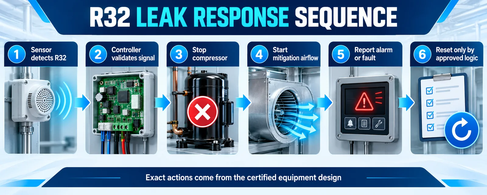
The controller must distinguish a refrigerant alarm from a sensor, wiring or communication fault. Define power-up behavior, warm-up handling, signal plausibility, open- or short-circuit detection where applicable, communication timeout, latching, reset and service indication.
The required mitigation action belongs to the certified equipment design. Depending on that design, the controller may stop selected equipment, command circulation airflow, close a valve or signal another control. Do not substitute a generic sequence. Verify the timing from release through sensor response, controller decision, actuator command and the resulting concentration reduction.
Validate with controlled releases and measured response
Instrument several candidate points with reference sampling probes. Release a controlled quantity or rate at each credible source under documented temperature, humidity, airflow and panel conditions. Record concentration versus time at the candidates, the installed detector output, the controller decision and the commanded mitigation response.
Test at least the approved unit orientations, fan off and relevant fan-on states, minimum and maximum specified airflow, clean and representative loaded-filter conditions, and the intended access-panel configuration. Repeat the worst cases sufficiently to distinguish a robust response from test scatter. The chosen point is the one that meets the system requirement in the slowest credible case, with engineering margin.

Common placement failures to remove during design review
Watch for these recurring problems:
- selecting the lowest sheet-metal point without mapping the leak jet;
- mounting directly in condensate or drain-overflow paths;
- qualifying only with the blower running;
- ignoring an approved horizontal or downflow configuration;
- hiding the sensing inlet behind insulation, a connector or a cable bundle;
- testing with a service panel removed when normal operation requires it installed;
- treating a component response time as the complete equipment response time;
- omitting sensor-fault behavior from the control specification.

Selecting a sensor for an OEM air-handler program
The sensing principle and electrical interface must fit the control architecture and qualification plan. Winsen’s ZRT510 R32 sensor module is listed as an NDIR R32 module; the current product export identifies PWM, RS485 and UART attributes. The MH-Z1542B-R32 is listed as an NDIR R32 sensor with UART. Interface and performance details must be confirmed against the current model datasheet before a design freeze.

For background on system architecture, see our A2L refrigerant detection guide, RDS guide for R32 and R454B equipment ja NDIR versus MOS comparison.
Information to send for an engineering review
Send the refrigerant and charge, equipment type, coil and cabinet drawings, all approved orientations, fan states and airflow range, candidate leak sources, controller interface, target alarm behavior, ambient range, annual volume and certification market. Winsen can then discuss a suitable sensing approach and the evidence needed for integration testing.
Contact Winsen for an R32 air-handler sensor review.
