
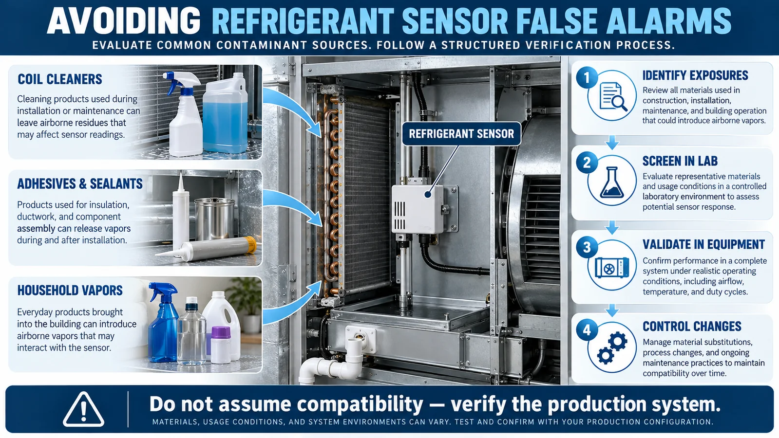
An HVAC refrigerant detector is installed in a chemical environment, not in clean laboratory air. Coil cleaners may be applied during service, adhesives and sealants may cure inside the cabinet, insulation and plastic parts can emit vapors, condensate can carry residues, and household aerosols can enter through return air. An unexplained signal in this environment may be a real refrigerant event, an interference response, a contaminated inlet, an electrical fault, or a control-system problem. Treating all unexpected signals as “false alarms” is unsafe and technically incomplete.
This guide presents a disciplined method for evaluating refrigerant sensor false alarms from chemicals in R32 and R454B HVAC equipment. It explains exposure mapping, material selection, controlled screening, production-intent equipment tests, alarm-versus-fault logic, recovery, service instructions, field evidence, and change control. It intentionally does not publish a universal list of safe or unsafe products. Chemical formulations, exposure levels, sensor variants, protective structures, temperature, humidity, and equipment airflow all influence the result.
Start by replacing the phrase “false alarm” with a cause tree
The phrase is often used before anyone has established that refrigerant was absent or that the detector behaved incorrectly. Build a cause tree instead. One branch covers real target gas reaching the sensor. Another covers nontarget vapor or liquid exposure. A third covers electrical and communication faults. Additional branches cover installation errors, blocked inlets, water, damaged wiring, controller logic, calibration state, and test-mode mistakes.
For each field event, preserve the raw detector signal, alarm and fault states, timestamps, fan command and feedback, temperature, humidity, recent service activity, materials used, and controller revision. If the system stores only a binary alarm, consider adding engineering logs during development. Without signal history, teams can confuse a slowly recovering chemical exposure with a recurring refrigerant leak or dismiss a real intermittent leak as nuisance behavior.
Do not suppress the symptom before identifying the cause. Increasing a delay, averaging channels, or changing a reset rule can hide a safety-relevant event. Any logic change needs a documented risk assessment and equipment-level verification.
Map chemical exposures across the product life cycle
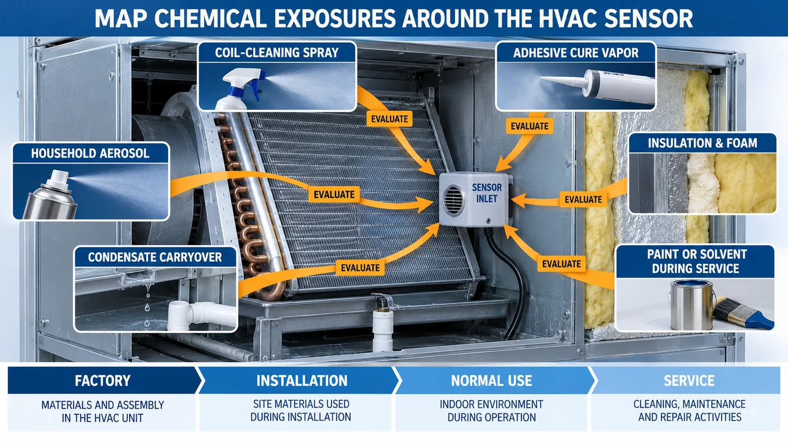
Create an exposure inventory for four phases: factory assembly, field installation, normal use, and service. Factory sources can include adhesives, conformal coatings, cleaning agents, lubricants, labels, foam, packaging, and recently molded plastics. Installation introduces sealants, pipe-joint work, paint, construction dust, and cleaners. Normal use introduces household aerosols, fragrances, alcohol-based products, cooking vapors, and cleaning products through return air. Service can produce concentrated coil-cleaner spray, solvent, disinfectant, leak-detection fluid, or adhesive cure vapor near the sensor.
Record the actual commercial material, formulation or safety-data reference, application quantity, cure state, location, airflow, and expected duration. A generic label such as “cleaner” is not enough because two products used for the same purpose can have different volatile components. Similarly, a cured adhesive and a freshly mixed adhesive are different exposure cases.
Prioritize credible exposure rather than testing an arbitrary chemical library. The objective is to cover the materials and use conditions that the equipment program permits, plus foreseeable service and household conditions identified by the risk assessment.
Understand why technology labels do not settle selectivity
NDIR, semiconductor, electrochemical, photoacoustic, and other sensing principles interact with gases differently, but a technology name is not a complete selectivity specification. Optical filters, source wavelength, path length, signal processing, compensation, enclosure materials, and calibration all matter. Two NDIR modules can behave differently toward the same vapor, and two variants in one product family can use different firmware or optical components.
Use supplier data to select screening candidates, but validate the exact model and suffix that will enter production. Ask for interference-test conditions, not only a statement such as “anti-interference.” Useful evidence identifies the material, vapor concentration, exposure duration, environmental conditions, response metric, recovery criteria, number of samples, and post-exposure target-gas check.
The installed protective cover can also change selectivity in practice. It may absorb or delay some vapors, retain condensate, or slow target-gas transport. Therefore both the bare sensor and production assembly may need testing for different engineering questions.
Coil cleaners require application-specific evaluation
Coil cleaners vary widely. They may be acidic, alkaline, solvent-containing, detergent-based, foaming, no-rinse, rinsed, scented, or disinfecting. The sensor can encounter an aerosol during application, vapor during dwell time, diluted liquid through condensate, or residue that releases vapor when the coil becomes wet or warm.
Define the permitted service procedure before designing the test. Record whether the equipment is powered, whether the sensor remains installed, which panels are removed, how the cleaner is applied, how long it remains, whether it is rinsed, and when the unit returns to operation. A concentrated direct spray into the sensor inlet is not representative if the instructions prohibit it; conversely, a remote low-level vapor test is insufficient if normal service occurs centimeters from the inlet.
Test both immediate behavior and recovery. After the cleaner exposure has cleared according to the service procedure, verify the sensor returns to its defined normal state and still responds correctly to the applicable refrigerant test. A sensor that appears quiet but has been poisoned or blocked is not a successful outcome.
Adhesives, sealants, foams, and insulation need cure-state controls
Cabinet adhesives and sealants can release volatile compounds during mixing and cure. Foam tapes, insulation, potting material, labels, and gaskets can also outgas, especially when new or heated. A prototype assembled weeks before testing may not represent a production unit shipped soon after assembly.
Build a material list tied to part numbers and approved suppliers. Identify application mass, bead geometry, cure time, temperature, and ventilation. Test the youngest credible assembly age as well as steady production conditions. If a supplier changes formulation without changing the commercial product name, your incoming change-control process should still capture the risk.
Placement can reduce exposure by separating the inlet from a concentrated cure plume, but the solution cannot block the refrigerant path. If a shield or airflow path is introduced, revalidate target-gas response. Material substitution may be preferable when a required adhesive produces an unacceptable signal or long recovery.
Household vapors enter through the return-air system
Room air can carry aerosol cleaners, alcohol-based sprays, fragrances, personal-care products, paint vapor, and cooking emissions. Whether these reach the detector depends on equipment type and sensor position. A detector inside the return-air path can experience a shorter, more concentrated pulse than a detector in a closed coil compartment. Fan speed, filter condition, room volume, and proximity of product use all influence exposure.
Design household-vapor tests from realistic scenarios. Do not instruct users or technicians to spray products into an operating unit. Laboratory testing should control the material quantity, air exchange, distance, temperature, humidity, and exposure duration. Include both a plausible nearby-use case and the maximum foreseeable case justified by the risk analysis.
The test result must distinguish a temporary detector signal from a system alarm and from permanent damage. Record raw output, control filtering, alarm status, diagnostics, recovery, and post-exposure refrigerant response. A material that does not trigger the final system could still reduce margin or extend recovery.
Condensate can transport residues to the inlet
Chemical exposure is not limited to vapor. Cleaner residue can dissolve in condensate, splash from a pan, wick along a harness, or dry on a protective opening. High humidity can also change adsorption, optical surfaces, or electronic leakage. AHRTI research and UL requirements treat humidity, poisoning, and environmental exposure as part of sensor reliability considerations, but the equipment manufacturer must still evaluate its specific geometry and materials.
Map normal and abnormal water paths. Include blocked drains, pump failure, unit tilt, wet filters, coil carryover, cleaning, and cable wicking. If the sensor can be wetted, determine the intended behavior: remain functional, issue a fault, recover after drying, or require replacement. That decision belongs in the control logic and service instructions.
After any liquid exposure test, inspect the inlet and electronics and run a target-gas verification. An absence of nuisance alarm is not enough if the liquid prevents later refrigerant detection.
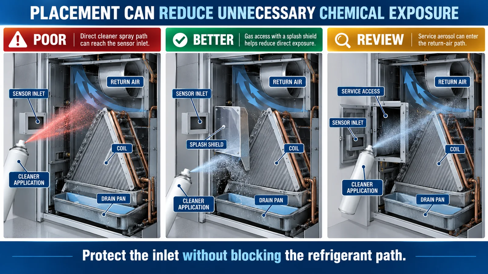
Placement can reduce unnecessary exposure without blocking gas
The best placement often balances two competing objectives: intercept a credible refrigerant plume and avoid direct cleaner spray, normal condensate, adhesive cure zones, or concentrated return-air contaminants. Use the exposure map together with the release-path map. Do not optimize one in isolation.
A splash shield, labyrinth, filter, membrane, or alternate inlet orientation can improve robustness, but each changes transport. Evaluate target gas, representative interferents, dust loading, condensation, cleaning, manufacturing tolerance, and aging in the final assembly. Make the keep-clear and service-protection requirements visible in drawings.
If the sensor must remain in a chemically exposed return path, consider whether the selected sensing principle and signal processing provide adequate selectivity and recovery. The answer must come from controlled evidence for the exact product, not a generic technology claim.
Build a controlled interference-screening matrix
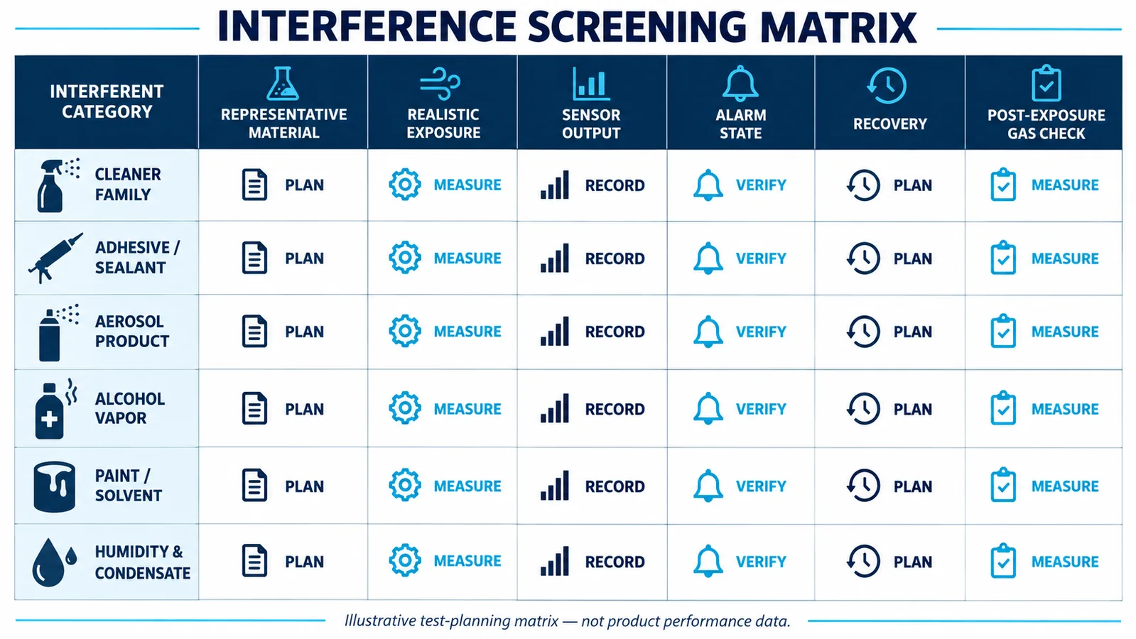
Rows should represent approved materials and credible field exposures. Columns should capture material identity, lot or formulation, preparation, exposure concentration or generation method, duration, temperature, humidity, airflow, sensor output, alarm state, fault state, recovery, and post-exposure target-gas verification. Separate bare-sensor screening from production-equipment confirmation.
Include controls. A clean-air baseline shows drift during the test. A reference instrument or validated vapor-generation method helps establish exposure. Replicates reveal sample variability. A target-gas check before and after exposure detects loss of sensitivity. If the study uses a surrogate material, document why it represents the permitted product family.
The matrix graphic below is illustrative planning content only. It does not assert that a cleaner, alcohol, adhesive, or solvent is compatible with any Winsen sensor. Compatibility must be established for the exact material and sensor under controlled conditions.
Use a safe and repeatable laboratory method
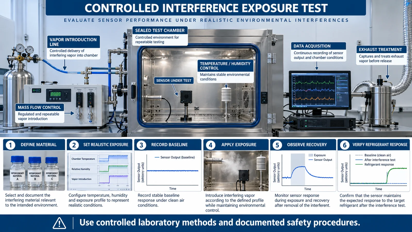
A suitable test system can control temperature, humidity, airflow, vapor generation, exposure time, sampling, and exhaust. Reference instrumentation should be appropriate for the test material and should not itself introduce contamination. All work must follow documented laboratory safety procedures and material handling requirements.
Begin with a stable clean-air baseline. Introduce the interference in a controlled way, record the full sensor signal and states, then purge or transition according to the protocol. Continue recording through recovery. Finally, apply the approved refrigerant verification method to confirm the detector’s safety function remains intact.
Avoid improvised tests such as placing an open solvent container beside equipment or spraying household products toward a sensor. They provide poor exposure control, can damage equipment, and create unnecessary hazards. A repeatable method is essential for comparing samples, firmware, protective covers, and material revisions.
Define pass criteria before seeing the results
Predefined criteria prevent teams from rationalizing unexpected behavior. Criteria may cover maximum permitted output shift, whether an alarm or fault occurs, recovery time, baseline stability, diagnostic behavior, and post-exposure target-gas response. Use the applicable standard, equipment safety concept, and controlled sensor specification to define them.
Different exposure classes may require different decisions. An approved factory adhesive may need to produce no nuisance response throughout production and shipping. A prohibited direct cleaner spray may be managed through service instructions and physical protection. A foreseeable household vapor may need to avoid alarm while preserving immediate target-gas detection. The risk analysis should explain the chosen treatment.
Do not use an undocumented software filter to force a pass. Filtering adds delay and can reduce response to a real refrigerant event. Any change to filtering, debounce, voting, baseline correction, or reset needs an end-to-end response-time and fault review.
Separate alarm, detector fault, and interference review
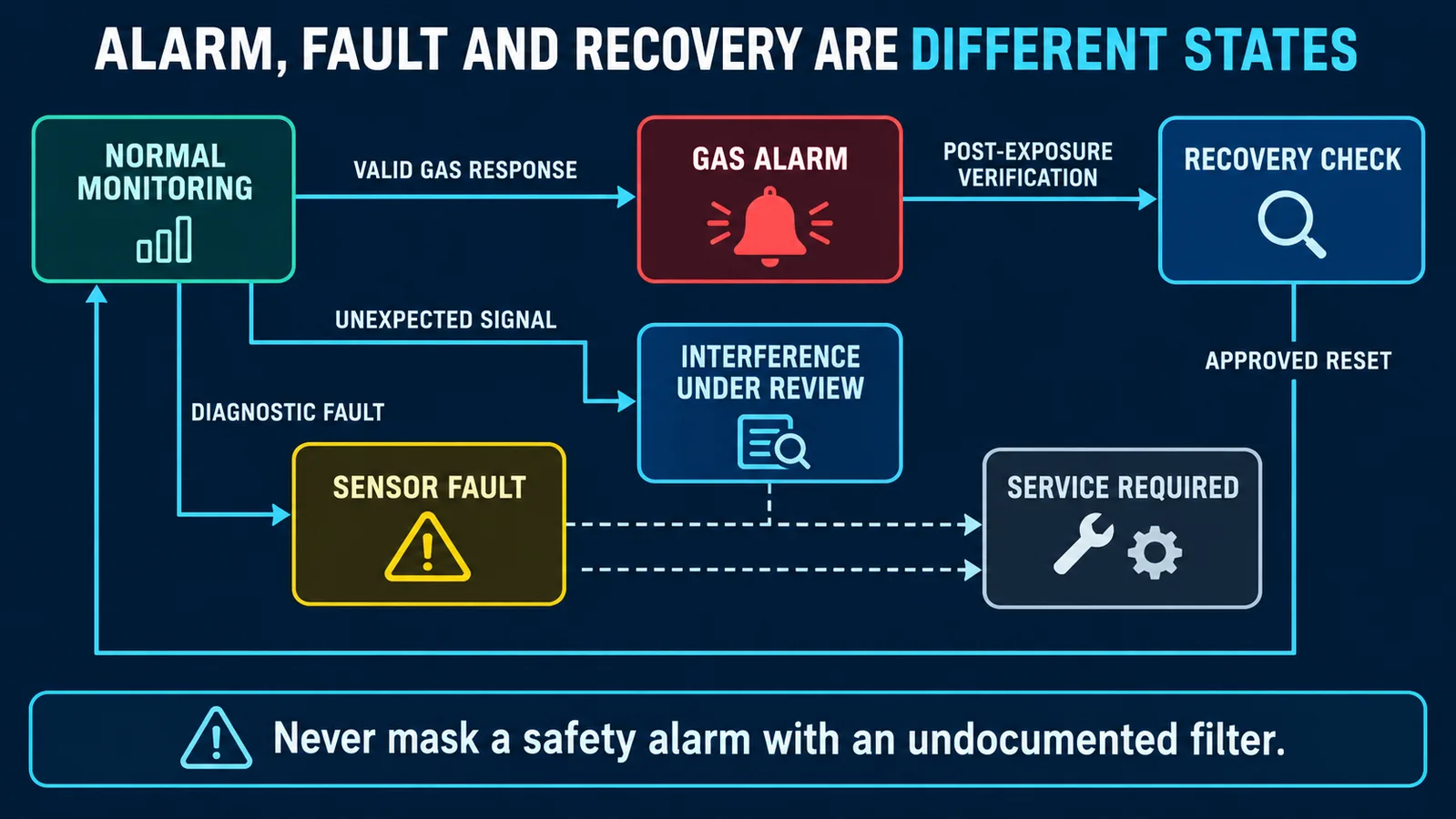
A confirmed refrigerant alarm, an electronic fault, and an unexpected but valid signal are not the same state. The controller should preserve these distinctions when the sensor interface supports them. A fault should not be converted into a healthy low reading; an alarm should not be cleared merely because a cleaning event is suspected.
Create explicit state transitions for normal monitoring, gas alarm, sensor fault, communication loss, recovery check, and service required. If the system detects an out-of-family signal or abnormal baseline, define whether it reports a fault, maintains mitigation, or requires service. The behavior must remain fail-safe according to the certified equipment design.
An interference investigation belongs after the immediate safety response, not instead of it. Field instructions can ask about recent cleaning or painting, but they should also require leak checks and diagnostic review appropriate to the equipment.
Recovery is part of compatibility
Some vapors produce a temporary signal that clears quickly; others can adsorb onto surfaces, condense, or alter a sensing element. Evaluate the entire recovery curve, not only the peak. A sensor that remains offset can cause repeated alarms, reduce detection margin, or make baseline algorithms behave unpredictably.
Define what “recovered” means: output within a controlled band, diagnostics normal, and successful target-gas response. Evaluate recovery at relevant temperature and humidity because evaporation and desorption can change. If power cycling affects the result, include both powered and unpowered recovery states in the analysis rather than relying on a reset as a cure.
When recovery is not reliable, the correct service action may be replacement. Make that decision explicit and provide an approved functional check after replacement.
Test combined and sequential exposures when credible
Real equipment can experience humidity plus cleaner vapor, adhesive cure followed by heat, or aerosol exposure on a dust-loaded inlet. Single-material screening is a necessary first step but may not cover credible combinations. Use the risk assessment to select combinations rather than testing every permutation.
Sequence can matter. A wet protective surface can retain a vapor; a cleaner can leave residue that later releases during heating; an adhesive plume can occur while the unit remains packaged. Record the order, interval, and environmental transition. Verify target-gas response after the final condition.
Combined tests are especially useful for validating a proposed protective cover or filter. They can reveal slower transport, retained contamination, or water blockage that individual dry tests miss.
Translate evidence into an approved-material list
Create a controlled list of factory materials, installation sealants, and service cleaners that were evaluated. Include exact manufacturer and product identity, approved application, restrictions, cure or rinse requirements, and the evidence report. A generic statement such as “use noncorrosive cleaner” does not control volatile composition or application near the detector.
Link the list to procurement and manufacturing change systems. New supplier, formulation, label, or process changes should trigger an impact review. Service documentation should name approved products or provide a controlled selection method and warn against direct application to the sensor inlet.
The approved list is not a universal endorsement of a chemical. It applies only to the documented equipment, sensor, installation, and procedure.
Investigate field events with evidence, not assumptions
Prepare a field-data package before launch. Useful records include detector signal history, alarm and fault codes, fan and compressor states, temperature and humidity, power interruptions, controller revision, unit model, sensor lot, installation photos, and recent service materials. Preserve the removed sensor and contaminated parts when a laboratory investigation is needed.
Use a structured decision tree: confirm whether refrigerant is present; inspect wiring and inlet; review event timing; identify recent chemical exposure; test the returned sensor in clean air and target gas; compare with a reference sample; and inspect the controller logic. Do not “prove” an interference by reproducing only a signal with an uncontrolled spray.
Aggregate field data by material, model, climate, sensor lot, and software. A pattern may reveal a specific service product, water path, or assembly-age issue that individual cases hide.
Control material, sensor, and firmware changes together
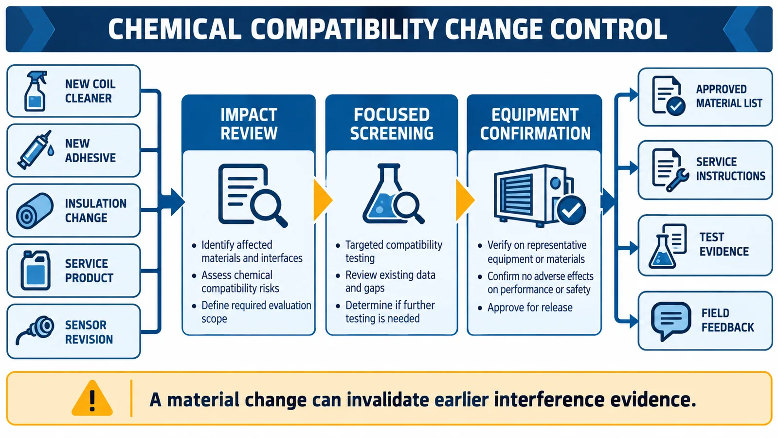
A new cleaner, adhesive, insulation, protective cover, sensor revision, or signal-processing update can invalidate earlier interference evidence. Apply a documented impact review that identifies changed exposure, transport, selectivity, filtering, recovery, and diagnostics. Use focused screening when the technical basis supports it and broader requalification when several factors change.
Keep test reports linked to the bill of material, approved-material list, drawings, firmware, and service instructions. Suppliers should notify the equipment manufacturer of relevant formulation or design changes. Incoming inspection cannot always detect a volatile-formulation change, so contractual change notification matters.
Design a field-event investigation that preserves evidence
When a customer reports an alarm during cleaning or renovation, the first service action should not be to reset repeatedly or replace the detector without records. Capture the timestamp, detector alarm and fault states, reported concentration or raw value if available, HVAC mode, fan state, room ventilation, product used, application method, approximate quantity, distance, duration and recovery history. Photograph the installed inlet and nearby residues before cleaning them away.
Compare other detectors in the same system. A response limited to one device may indicate a local exposure or blocked path; simultaneous events can indicate a shared return-air source, power disturbance or actual refrigerant condition. Check refrigerant evidence independently rather than assuming that the presence of a cleaner proves the alarm was false. Pressure, service history and approved leak-check procedures may be needed.
Preserve the removed unit in a sealed, labeled package when laboratory examination is justified. Record firmware, configuration and serial or lot information. A no-fault-found bench result after hours of clean-air recovery does not reconstruct the field exposure; event logs and site details provide the missing context.
Turn screening results into practical engineering limits
A compatibility report should not end with “pass” or “fail.” Define the maximum evaluated use condition, required ventilation or cure time, prohibited direct spray, minimum separation from the inlet if supported, recovery action and any inspection after exposure. Link those limits to manufacturing work instructions, installer manuals and service training.
For materials applied inside equipment, control both formulation and application mass. A bead of adhesive used in qualification does not cover a field technician filling a cavity with the same product. For cleaners, control dilution, rinse, dwell time and whether the fan operates during or after application. For occupant products, emphasize ventilation and the difference between normal incidental use and deliberate application into the return grille.
Use complaint trends as a feedback loop. Group events by chemical class, unit geometry, sensor revision, climate and service procedure. A cluster may reveal an untested combination, an inlet exposed to concentrated return air, or a firmware change that altered persistence. Trend data should guide targeted testing rather than encourage a broad reduction in alarm sensitivity.
Avoid three tempting but unsafe shortcuts
First, do not mask repeated events with a long delay unless the complete safety response remains compliant and the root cause is understood. Second, do not relocate the sensor away from chemicals without revalidating refrigerant transport. Third, do not publish an unlimited “immune to cleaners” claim from a few chamber tests. Formulations, concentrations and mixtures vary, and material damage may appear after repeated exposure even when no immediate alarm occurs.
Product integration example: multi-refrigerant NDIR sensing
Winsen’s MH-441D is listed in the verified WooCommerce export as an NDIR refrigerant sensor for R32, R454B, R410A, and R134a, with analog-voltage and UART interfaces listed. Because the export notes an output-description conflict, the exact interface and electrical details must be confirmed from the current controlled datasheet before selection.

Do not infer cleaner, adhesive, or household-vapor compatibility from the NDIR principle or product summary. Request controlled interference evidence relevant to the application and run equipment-specific screening. Confirm refrigerant calibration, supply, output, diagnostic behavior, environmental limits, response definition, protective structure, and certification scope.
Related engineering guides include RDS design for R32 and R454B equipment, R32 leak-alarm control sequencing, y drain-pan, blower, and return-air placement tradeoffs.
What to send for an interference review
Provide the target refrigerant, sensor variant, equipment type, proposed location and cover, raw interface data, alarm and fault logic, complete factory material list, approved cleaners and service procedure, household exposure scenarios, temperature and humidity range, annual volume, and certification market. If a field event prompted the review, include event logs, recent service materials, installation photos, and the returned sensor.
Winsen can review the candidate module interface and help structure an interference-screening matrix. Final compatibility and equipment qualification remain part of the OEM’s controlled safety program.
Contact Winsen for a refrigerant-sensor interference review.
Referencias
- Soluciones UL: requisitos actualizados para sistemas de detección de refrigerantes
- Soluciones UL: Inspección de sistemas de detección de refrigerante en equipos HVAC
- Soluciones UL: respuesta de sensores en sistemas HVAC
- Iniciativa de investigación de refrigerantes inflamables del AHRI
- AHRTI 9009: Detección de fugas de refrigerantes A2L en equipos HVACR
- Winsen MH-441D product page
