
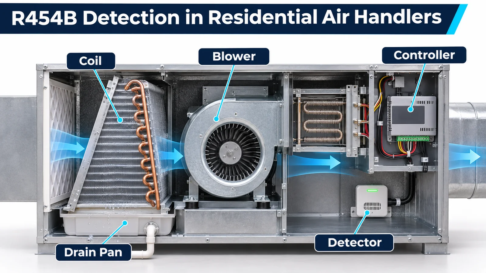
Residential air handlers are frequently sold as convertible equipment. The same cabinet may operate in upflow, downflow, horizontal-left or horizontal-right orientation, with different drain pans, heat kits, filters and coil configurations. A refrigerant detector that is correctly exposed in one arrangement may be above the release source, behind a barrier or in a wet zone after conversion.
That is why R454B sensor placement in an air handler must be defined by orientation-specific gas transport and system response. Refrigerant properties matter, but they do not replace analysis of release momentum, cabinet geometry, fan state, drain-pan barriers, heat and the occupied-space boundary. The location must work as part of the released equipment configuration.
This guide gives OEM engineers a structured method. It does not prescribe a universal height, detector count, alarm threshold or mitigation sequence. Use the current applicable equipment requirements, controlled refrigerant information, certification program and detector documentation for the target market.
1. Define Every Released Air-Handler Configuration
Begin with a configuration table. Include cabinet sizes, coil families, upflow/downflow/horizontal orientations, left/right discharge, factory and field-installed heat kits, auxiliary drain pans, filter bases, return boxes, supply plenums, zoning accessories and approved sensors. Record maximum refrigerant charge and the connected outdoor-unit combinations.
The detector decision must cover the combinations the installation instructions allow. A test on one upflow cabinet cannot automatically support a horizontal cabinet with a different drain pan and blower relationship. If a configuration is not evaluated, either exclude it or provide a controlled location and validation path for it.
Define the safety function for each configuration: what constitutes valid monitoring, which controller receives the detector output, what actions occur for alarm and fault, which fan or heat stages are affected, how annunciation works and how recovery occurs. The detector is one element; the complete air handler must demonstrate the intended physical response.
2. Map Credible R454B Release Sources
Overlay the refrigerant circuit on the cabinet. Mark coil headers, distributors, return bends, brazed joints, expansion device, service connections, sensing ports and any field joint within or adjacent to the air handler. Include areas where a release can impinge on sheet metal, insulation or the drain pan.
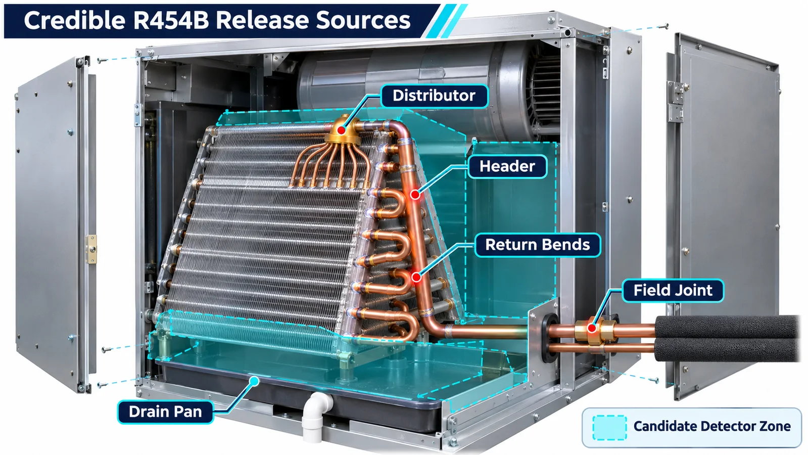
Separate release sources by initial direction and compartment. A distributor leak can enter the coil face or pan region; a return-bend leak may jet toward a side panel; a field joint can release near a line-set opening. Refrigerant can follow tubing and insulation before entering the main airstream. The first seconds may not resemble a uniform cloud.
Use the map to choose test release points and detector candidates. Preserve it as a controlled design artifact. When a coil supplier, tube route, cabinet or line-set opening changes, the team can assess whether transport and validation are affected.
Do not choose only the most obvious leak source. Coverage should address the credible sources defined by the equipment safety analysis and applicable requirements. Record why any source is excluded or covered by another measure.
3. Treat Orientation as a New Gravity and Barrier Problem
When an air handler rotates, every relationship changes: coil height, blower position, pan surface, drain openings, heat section, panel seams and detector orientation. A low point in upflow may become a vertical side wall in horizontal installation. A bracket designed to drain may become a cup.
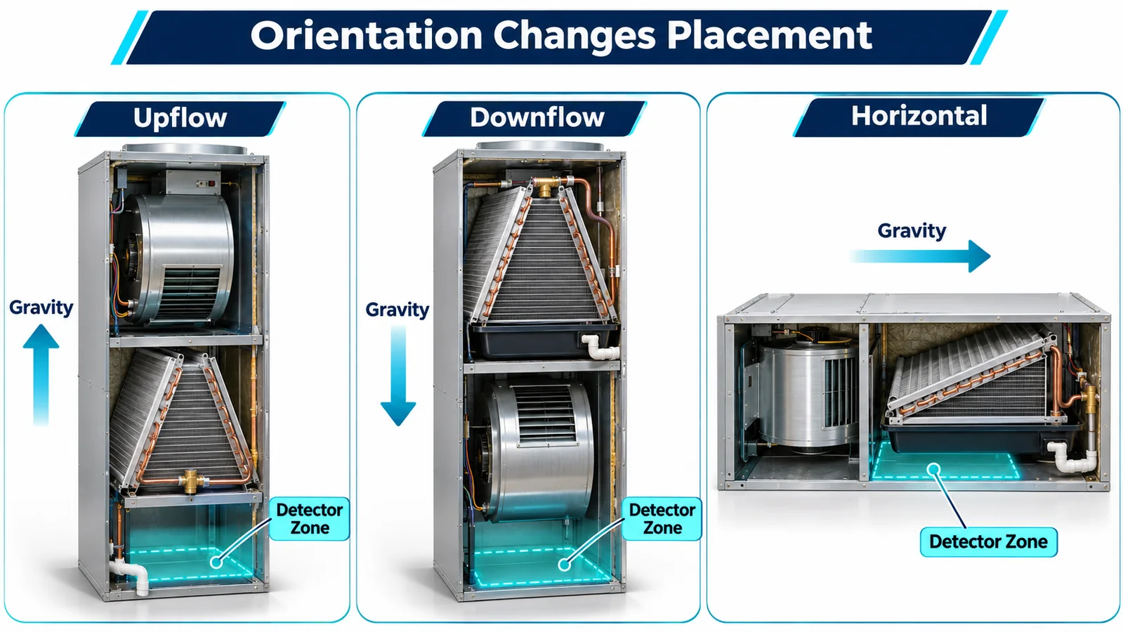
For each released orientation, redraw the physical stack from the direction of gravity. Identify potential collection zones, barriers and paths to the occupied space. Mark the active and auxiliary drain pans. Verify whether the detector’s specified orientation and inlet direction remain valid.
Convertible equipment often needs an orientation-specific bracket position. Use dedicated holes, labels or keyed features that make the correct position clear. If the sensor remains fixed to the cabinet while the coil or blower moves, verify that the gas path still connects credible sources to the inlet.
Installation instructions should show the exact location for each orientation with real cabinet features, not a generic “near the coil” statement. Field conversion must preserve harness routing, inlet clearance and drainage.
4. Compare Fan-Off and Fan-On Transport
With the blower off, released R454B may migrate under momentum, density differences and natural convection. It can collect behind the pan lip, below a coil, in a return box or along cabinet seams. With the blower on, the same release can be entrained, diluted and moved through the supply duct quickly.
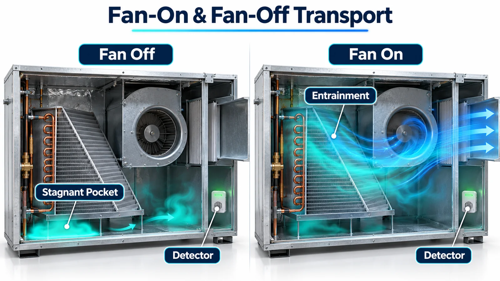
Evaluate at least standby, startup, normal blower operation, fan delay, fan rundown and relevant fan-fault conditions. Include speed stages or variable-speed airflow that can redirect local flow. A detector placed directly in a high-velocity jet may see dilution; a detector in a quiet pocket may respond at fan-off but be bypassed at fan-on.
The limiting state may differ by release source and orientation. Build a matrix rather than searching for one intuitively “worst” case. Use airflow visualization and modeling to understand mechanisms, then verify with production-intent hardware and controlled releases.
If mitigation depends on starting or continuing the blower, validate delivered airflow with the released filter, coil, heat kit, duct static and zoning state. A controller command is not proof that required airflow occurred.
5. Account for Drain Pans and Condensate
Drain pans are large barriers and wet surfaces. They can collect refrigerant below the coil, divert a release toward a cabinet edge or isolate a detector on the wrong side. Their geometry changes between vertical and horizontal configurations. Auxiliary pans and field drains add more variation.
Map liquid and gas paths together. Position the detector outside standing-water and overflow zones while preserving access to representative gas. Use cable drip loops, protected connectors and open splash shields. Avoid fine screens or covers that trap cleaner and delay diffusion.
Test with dry and wet pans where moisture changes transport or exposure. Include drain blockage, tilt and condensate conditions within the installation envelope. After water exposure, verify diagnostics and gas response; visual dryness alone does not prove recovery.
Cleaning procedures should protect the inlet from coil cleaner and debris and ensure protection is removed before operation. Evaluate approved chemicals for material compatibility and credible cross-response using controlled supplier guidance.
6. Keep Electric Heat and the Occupied Boundary in View
Electric heat kits introduce hot surfaces, power switching and airflow changes. The detector must remain within its environmental limits and the controller must manage heat according to the released mitigation sequence. Do not place a sensor where radiant or convective heat changes its response beyond the characterized envelope.
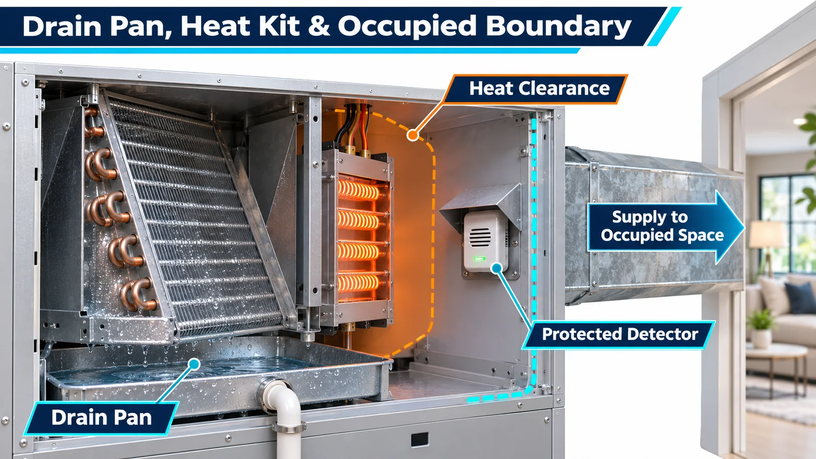
Map all potential ignition sources and their power paths. If an alarm requires de-energizing heat, verify the actual contactor or relay state and account for residual heat. If the blower is part of mitigation, analyze the interaction between heat shutdown and fan operation.
The supply and return ducts connect the cabinet to occupied space. Identify how quickly a release can leave the unit and where the detector sits relative to that path. A detector downstream of the coil may respond during blower operation but not during standby accumulation. A return-side detector may miss a release immediately driven into supply air.
The applicable equipment requirements and certified design determine acceptable locations and actions. Document how the chosen detector and control sequence satisfy the released system architecture; do not infer compliance from component placement alone.
7. Select Candidate Zones From Evidence
Candidate zones should meet several constraints simultaneously:
- transport from every covered release source in each orientation;
- acceptable exposure in fan-off and fan-on states;
- clear inlet path at cabinet and accessory tolerance extremes;
- separation from direct condensate, overflow and cleaning spray;
- operation within temperature, humidity and vibration limits;
- protection from heat and electrical hazards;
- stable bracket datums and repeatable field conversion;
- connector, harness and service access;
- no unacceptable obstruction to airflow or maintenance.
Use a coverage matrix with release sources as rows and candidate zones as columns for each orientation/state. Mark direct coverage, indirect coverage, uncertain coverage and no coverage. Test the uncertain and limiting combinations.
Avoid reducing the decision to height. Heavier-than-air behavior can inform hypotheses, but local flow, momentum, surfaces and barriers determine actual concentration. UL Solutions notes that installation instructions specify locations where leaked refrigerant is expected to collect and that multi-position equipment may require location changes by orientation. The equipment evidence remains decisive.
8. Decide Detector Count by Independent Zones
One coil does not always mean one detector, and one detector does not always cover one cabinet. Multiple coils, separate drain-pan regions, bulkheads or orientation-dependent pockets may create independent gas zones. Conversely, one well-validated zone may cover several nearby release sources.
Determine count from the coverage matrix and single-fault analysis. For each detector, identify the sources and orientations it covers. If a detector fails, define the equipment response; do not assume another sensor provides equivalent coverage unless transport and controller logic support it.
For multi-position products, detector count may remain the same while mounting positions change. Use keyed brackets and instructions to prevent a vertical-position sensor from remaining in an invalid horizontal location.
The controller should preserve sensor identity. A generic alarm input without location or configuration context can make service and fault handling ambiguous. For digital networks, address duplicate IDs and misassigned channels.
9. Define the Detector Interface Contract
Specify the exact gas variant, supply, startup behavior, validity indication, measurement units, update timing, alarm semantics, fault codes, timeout, electrical levels, communication checks and recovery. Treat warm-up and invalid data as explicit controller states, not as zero concentration.
If the detector provides concentration and a discrete or protocol alarm, define which value owns the safety decision and how disagreement is handled. Avoid duplicate thresholds scattered in sensor, controller and supervisory software. Keep the released configuration traceable.
Monitor stale data. A plausible value repeated indefinitely is not valid monitoring. Use sequence counters, timestamps, update watchdogs or other interface-appropriate checks. Detect open, short and out-of-range behavior for analog channels.
Confirm that the installed sensor is calibrated for R454B. A visually identical R32 or other refrigerant variant may communicate correctly while applying the wrong gas response. Use part control and electronic/configuration checks where possible.
10. Separate Alarm, Fault and Mitigation Failure
The controller should distinguish a valid R454B alarm from detector diagnostic fault, communication fault, power loss, invalid data and mitigation-device failure. These states may share protective actions but need different annunciation, logs and service procedures.
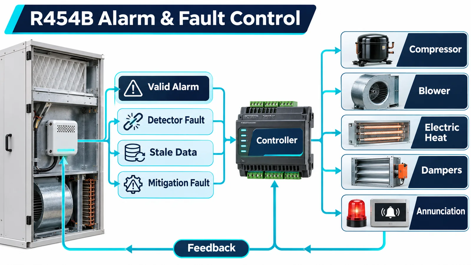
Create a state table for startup, normal, alarm, fault, stale data, actuator fault, recovery and service mode. Define compressor, blower, electric heat, zoning/dampers, annunciation and remote signal behavior for each. Applicable equipment requirements and the released safety analysis determine the exact actions and timing.
Normal thermostat commands must not override the safety state. Service and test modes need access control, clear indication and timeout or controlled exit. Reset should require the released conditions, such as valid data and confirmed actuators, rather than simply clearing a bit.
Where the controller depends on the blower, heat contactor or damper position, use appropriate physical feedback. A command echo alone does not prove the physical state changed.
11. Validate Actuator Feedback and Fault Injection
Identify the physical outcomes required by mitigation: compressor stopped, blower running or stopped as designed, heat de-energized, dampers positioned, alarm active. Select feedback signals that demonstrate those outcomes within the architecture.
Test welded or stuck relays, failed fan, missing speed feedback, open heat contactor feedback, closed damper and communication loss. Verify controller priority, annunciation, logs and recovery. Fault injection should use production I/O and firmware, not only a software simulation.
Power disturbances deserve special attention. Detector and controller may reset at different thresholds. Test brownout, one-sided power loss, rapid cycling and communication restart. Ensure old values are not accepted after reset.
If a building or zone controller participates, verify that local equipment protection remains deterministic during network loss. Field wiring and zoning configurations included in the installation envelope should be represented.
12. Integrate the ZRT512E Conservatively
Winsen lists the ZRT512E family for R32 and R454B detection with an NDIR principle and RS485-oriented integration in current product information. Certification language in the local product export is conditional and must not be repeated as a released claim without current certificate evidence. Exact gas variant, range, response, power, protocol, environmental limits, dimensions, diagnostics and qualification status must be confirmed from controlled project documents.

Request the full model code, refrigerant calibration, protocol revision, startup/validity behavior, fault definitions, mechanical drawing, inlet restrictions, environmental limits, drift/life evidence, EMC and vibration evidence, and change-notification process. Ensure the controller implementation matches the ordered variant.
A dual-gas family description does not mean one installed module automatically recognizes or measures both refrigerants correctly. The released equipment configuration must identify the calibration and interpret its units accordingly.
The air-handler OEM remains responsible for installed exposure, orientation-specific location, controls, manufacturing and equipment-level evaluation. The module does not make the complete air handler compliant by itself.
13. Build an Orientation-Specific Validation Matrix
The matrix should include:
| Faktor | Reprezentativní úrovně |
|---|---|
| Orientace | upflow, downflow, horizontal-left, horizontal-right as released |
| Release source | distributor, headers, return bends, joints, field connection areas |
| Fan state | off, startup/delay, operating speeds, rundown, relevant fault |
| Drain condition | dry, wet, tilt, blockage/overflow conditions in the safety analysis |
| Heat/accessory | no heat, released heat kits, filter and approved accessories |
| Cabinet | size, coil, panel/seal tolerances, return/supply configurations |
| Prostředí | relevant temperature and humidity conditions |
| Controls | alarm, detector fault, stale data, power interruption, actuator failure |
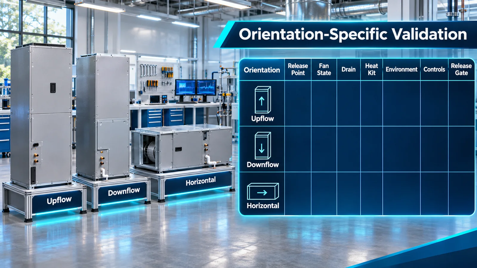
Define release method and acceptance criteria before testing. Synchronize detector output, controller state, command timing, actuator feedback and local concentration instrumentation. Record full hardware/software configuration and repeat the limiting cases.
Use production-intent brackets, harnesses, drain pans, panels, heat kits, filters and firmware. A temporary sensor in an open cabinet is development evidence, not release evidence.
14. Preserve the Location Through Manufacturing and Installation
Control detector variant, bracket position, orientation, inlet clearance, harness route, connector engagement and software configuration. Use asymmetric features and inspection points. Prevent insulation, sealant, labels and cable loops from entering the gas-path keep-out.
For field-convertible equipment, instructions must show relocation or rotation steps and post-conversion verification. Make unused holes or alternate positions unambiguous. If different brackets are required, control them by configuration.
End-of-line checks should verify identity, communication, validity and required controller actions. Mechanical inspection and functional audit are still needed because internal self-test cannot prove gas access or correct position.
Field service should protect the inlet during cleaning, restore the qualified route and verify final closed construction. Replacement parts must match refrigerant calibration and interface revision.
Manufacturing audits should also compare the physical unit with the orientation record stored by the controller. A mechanically horizontal unit configured as upflow can pass basic communication tests while using the wrong response assumptions. Include cabinet orientation, bracket position and software parameter in one inspection record. When field conversion is allowed, require the same reconciliation after conversion and preserve evidence with the equipment serial number.
15. Engineering Release Checklist
Confirm that:
- Every allowed cabinet, coil, orientation, heat kit and accessory is in the configuration plan.
- Credible R454B release sources are mapped physically.
- Gravity, pan barriers and gas paths are redrawn for each orientation.
- Fan-off, fan-on, delays, speeds and relevant faults are covered.
- Drainage, overflow, cleaning and condensation do not defeat the detector.
- Heat, electrical and occupied-space boundaries are included.
- Candidate location and detector count follow coverage evidence.
- The controller knows refrigerant, unit, validity, alarm and fault context.
- Alarm, diagnostic fault and mitigation failure are distinct states.
- Critical commands use suitable feedback and fault response.
- Product claims rely on current controlled evidence.
- The validation matrix covers every released orientation and limiting combination.
- Production, field conversion and service preserve the qualified position.
Any assumption without evidence should become an engineering action before release.
16. Review Design Margin and Change Triggers
After testing, compare cases to find the slowest gas arrival, lowest detector exposure, longest controller/actuator response and most difficult recovery. A pass/fail result alone does not show whether normal manufacturing or installation variation can erase the margin.
Probe sensitivity by shifting detector position within tolerance, changing cabinet leakage, filter loading, fan speed and pan wetness. If a small change produces a large response difference, improve geometry or controls rather than relying on a narrow inspection limit.
Define regression triggers for coil, pan, bracket, blower, heat kit, insulation, cabinet, sensor, firmware and threshold changes. The design record should identify which orientation and release tests represent the current limiting cases.
Include aging where required: fan degradation, detector drift, corrosion, contamination and service movement. Maintenance instructions should preserve the airflow and inlet conditions assumed in validation.
17. Design Field Conversion as a Controlled Process
Convertible air handlers place part of the final safety configuration in the installer’s hands. Treat orientation conversion like a controlled assembly operation. The instructions should identify the released orientation, active drain pan, coil/blower relationship, detector bracket position, inlet direction, harness clips and software configuration. Provide clear photographs or diagrams tied to cabinet features.
Use hardware that supports the process. Captive fasteners, keyed brackets, dedicated holes and retained harness length reduce interpretation. Cover or eliminate unused positions that could accept the sensor incorrectly. If the same bracket rotates, ensure drainage and connector load remain valid in every allowed position.
Require a post-conversion inspection and controller check. Confirm detector identity, position, open inlet, connector, route, valid data and configured orientation. If the controller uses an orientation parameter, protect it from casual change and ensure it agrees with the mechanical build. A label alone cannot reconcile conflicting hardware and software.
Installation variability should appear in validation. Include realistic duct transitions, return bases, filters, access panels and field tolerances. Evaluate the minimum clearances allowed by instructions. If a field-installed part can block the detector or alter the gas path, redesign the interface or restrict the installation.
Feed field audit results into product engineering. Repeated incorrect placements indicate that the design or instructions are not sufficiently error-resistant. Improve physical poka-yoke before relying on more warning text.
18. Coordinate Service and Replacement
Service can disturb the qualified position even when the detector is not the repair target. Coil cleaning, blower removal, heat-kit service and drain maintenance may move harnesses, insulation or brackets. Map these tasks and define whether the detector stays installed, is protected or is removed.
Protect the inlet from cleaner, water and debris with a controlled temporary method. Make removal of protection an explicit closeout step. After panel closure, verify valid monitoring and any required alarm/fault response. Internal self-test does not prove gas access or correct orientation.
Replacement parts must be R454B-calibrated and compatible with the controller. Use keyed parts, identity checks and configuration records. Preserve the exact bracket and harness route. If service changes firmware or controller board, verify the gas/unit interpretation and released threshold configuration.
Record detector part/revision, equipment orientation, controller software, reason for service and final test. This traceability helps distinguish sensor failure from installation, contamination, transport or control problems and supports targeted product improvement.
Závěr
R454B detector placement in a residential air handler is configuration-specific. Orientation changes gravity, barriers, drainage, airflow and the relationship between release sources and the occupied-space path. The robust design maps those changes, gives the controller clear validity/alarm/fault information and proves the complete response on production-intent hardware.
For an engineering review, provide the refrigerant and charge, cabinet/coil list, orientation and accessory matrix, refrigerant-circuit drawing, candidate locations, fan modes, controller interface, mitigation sequence, environmental limits, annual volume and target certification market.
Reference
- UL Solutions — Kontrola systémů detekce chladiva v zařízení HVAC
- UL Solutions — Aktualizované požadavky na systémy detekce chladiva
- UL Solutions — Odezva senzoru v systémech HVAC
- AHRI – Iniciativa pro výzkum hořlavých chladiv
- AHRTI 9009 — Detekce úniku chladiv A2L v zařízení HVACR
- Winsen — Refrigerant Sensor Solutions
