
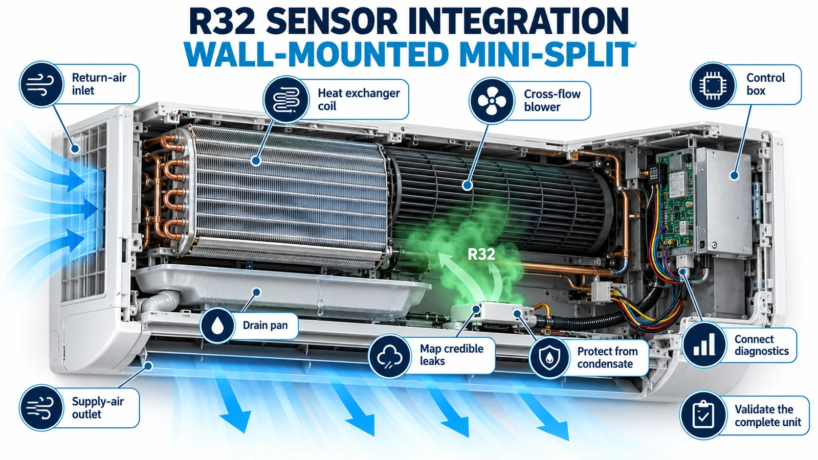
Integrating an R32 detector into a wall-mounted mini-split is a system engineering task. The sensor must encounter a credible leak in time, survive a wet and thermally changing cabinet, communicate reliably with the indoor controller, distinguish a gas alarm from a component fault, and initiate the equipment response defined by the certified design.
This guide turns those requirements into a practical OEM workflow. It focuses on production-intent wall-mounted indoor units. The exact detector location, threshold, response timing and mitigation sequence must follow the applicable equipment standard, certification program and manufacturer instructions.
Define the complete safety function first
Write a short functional specification before choosing a bracket. Identify the R32 charge, indoor-unit volume, refrigerant-bearing components, intended markets, sensing interface, alarm condition, diagnostic conditions, mitigation commands, reset criteria and required evidence.
Treat the detector, harness, control board, firmware, blower and user indication as one chain. A responsive sensing element does not prove that the assembled unit will mitigate a leak. UL’s guidance for integral refrigerant detection systems emphasizes that the RDS is part of the certified equipment and that installation details come from the equipment instructions.
Map credible release points inside the indoor unit
Mark the flare connection, distributor, coil header, return bends, braze joints and service tubing on the production drawing. For each source, record the possible jet direction, nearby surfaces, cabinet openings and the operating pressures or states relevant to the qualification plan.
The source closest to the detector is not necessarily the limiting case. A jet can pass behind the heat exchanger, strike a plastic wall, discharge toward the room or become trapped beside the electrical box. Test sources on opposite sides of the coil when the refrigerant circuit creates distinct paths.

Use dispersion physics to screen candidate zones
R32 has a molecular weight of about 52.02 g/mol, compared with roughly 29 g/mol for dry air. This supports a downward buoyancy tendency for a sufficiently concentrated R32-rich cloud. Yet the initial jet, cooling during expansion, entrainment and indoor-unit airflow can redirect and dilute it.
Experimental work on operating wall-mounted R32 air conditioners found that leak location and air-supply conditions affected the concentration distribution. A 2024 experiment-and-simulation study likewise found different diffusion behavior for different leak locations. Its reported best detector area was specific to the tested unit, between the electrical box and the front heat exchanger. Use such findings to define candidates, not to copy a universal coordinate.
Select a candidate that is low, dry, open and serviceable
A lower internal zone near the coil may be a useful candidate because it can intercept downward-moving refrigerant before discharge to the room. Screen it against four practical conditions:
- the sensing inlet lies on the plume path for every credible source;
- normal condensate, blocked-drain overflow and cleaning spray do not reach it;
- the inlet clearance and mounting attitude follow the controlled sensor datasheet;
- a technician can inspect or replace the part without changing its orientation.
Do not place the inlet flat against plastic, insulation, wiring or the pan wall. Control the bracket and harness length so production units reproduce the qualified geometry.

Keep condensate and cleaning fluid out of the sensor
Wall-mounted indoor units create condensate directly above the lower cabinet. Review the normal drip path, drain-pan slope, drain outlet, blocked-drain overflow, transport tilt and the spray pattern used during coil cleaning. A detector can be close to a low plume path without becoming part of the water path.
Add shields only after checking that they do not block gas transport or create a stagnant cavity. Consider surface tension and capillary paths along wires. A cable entering from above can carry water to a connector unless routing, drip loops and sealing are deliberately controlled.

Integrate power, signal and diagnostics with the control board
Confirm the exact model’s supply range, current demand, startup behavior, output type, connector pinout, communication timing and diagnostic definitions from the current controlled datasheet. Budget both steady-state and transient load at temperature and supply-voltage corners.
Keep low-level sensing and communication conductors away from inverter, motor and mains wiring. Define harness shielding or grounding only as required by the design. Validate connector retention, vibration, cable strain, electrostatic discharge, conducted and radiated immunity, and the controller’s response to communication timeout or implausible data.

Separate a gas alarm from a sensor fault
A gas alarm means the channel detected the defined refrigerant condition. A sensor fault means the detection function may be unavailable or unreliable. Give them distinct controller states, event logging and service information.
Define behavior during power-up, warm-up, communication loss, out-of-range output, supply interruption and recovery. Avoid firmware that silently treats a missing detector as “no gas.” The system response for an alarm and the safe handling of a detection-system fault must be documented and validated separately.
Program the equipment response as a timed sequence
The certified equipment design determines the response. It may stop refrigerant-producing operation, command a specified indoor airflow state, open other airflow paths, signal a fault or require service before reset. Do not import a generic sequence from another indoor unit.
Measure the full timeline: release starts, refrigerant reaches the sensor, output changes, controller confirms the condition, the command reaches the blower or other actuator, and the concentration is reduced according to the defined criterion. Include failure cases in which the blower or communication path is unavailable.

Validate the production-intent mini-split
Use the released cover, filters, coil, pan, wiring and insulation. Instrument several candidate locations with reference probes. Conduct controlled releases at the credible points and record concentration versus time, installed-detector output, controller events, blower state and recovery.
The matrix should include fan off, normal fan speeds, the specified mitigation state, relevant louver positions, clean and representative loaded filters, cover installed, temperature and humidity corners, and foreseeable drain conditions. Repeat the slow cases and preserve engineering margin for unit-to-unit variation.

Design the production and service controls
Add poka-yoke features so the sensor cannot be installed backward or on the wrong boss. Use a keyed connector, controlled fastener, defined harness clips and an end-of-line check that can distinguish a connected functioning channel from an open circuit.
Service instructions should specify the exact replacement part, sensing-face orientation, post-service test and disposal procedure. If cleaning is allowed, define which fluids, spray directions and drying steps are compatible with the assembly. Record firmware and sensor variants in the configuration system.
Match the sensor architecture to the mini-split
Winsen’s ZRT512J refrigerant detection module is listed in the official WooCommerce export as an NDIR module for R32, R454B and R290, with PWM, RS485 and UART attributes. The MH-Z1542B-R32 is listed as an NDIR R32 sensor with UART. These are initial architecture inputs only. Confirm the exact gas variant, dimensions, interface, power, lifetime, environmental range and qualification evidence against the current controlled datasheet before design freeze.

Related engineering guides: R32 sensor placement in a ducted air handler, R32 density, airflow and enclosure geometry, a How to choose an A2L refrigerant sensor.
Information for an OEM integration review
Send the refrigerant and charge, indoor-unit drawings, coil and drain geometry, leak-source list, fan and louver states, controller interface, alarm target, ambient limits, annual volume and certification market. Winsen can then review the sensing architecture and the inputs required for a production-intent validation plan.
Contact Winsen for a mini-split R32 sensor review.
Reference
- UL Solutions: Inspecting Refrigerant Detection Systems in HVAC Equipment
- UL Solutions: Updated Requirements for Refrigerant Detection Systems
- AHRI Flammable Refrigerants Research Initiative
- Applied Energy: Experimental Study on R32 Leakage from Wall-Mounted Air Conditioners
- Journal of Refrigeration: Influence of R32 Leak Detection Position on Indoor Safety
- NIST Chemistry WebBook: Difluoromethane (R32)
