
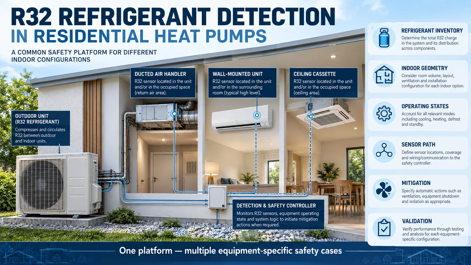
Residential heat pumps are moving toward lower-GWP refrigerants such as R32, but the detector integration problem is not solved by choosing a sensor and connecting it to a controller. A complete design must relate refrigerant inventory to occupied space, locate the sensing inlet in the actual indoor-unit gas path, supervise the sensor and wiring, coordinate equipment-specific mitigation, and prove the result in cooling, heating, defrost-related, standby, fault, production, and service conditions.
This engineering checklist addresses R32 heat pump refrigerant detection for ducted air handlers, furnaces with coils, wall-mounted units, ceiling cassettes, and floor consoles. It is intended for OEM product engineers and functional-safety teams. It does not define a universal sensor location, concentration threshold, charge limit, or control sequence. Those requirements depend on the applicable standard, certification program, equipment construction, room assumptions, and controlled manufacturer instructions.
Gate 1: Freeze the equipment configuration before judging coverage
Begin with an exact configuration list. Record the outdoor unit, indoor unit, coil, cabinet or casing, line-set limits, maximum charge, optional heat, filters, drain kits, panels, zoning accessories, valves, controller, sensor variant, bracket, harness, and firmware. If a platform supports several indoor-unit types, do not treat “same outdoor unit” as evidence that one detector design covers all of them.
Configuration control matters because a small change can alter gas transport. A wider coil, different blower wheel, added electric-heat rack, alternate filter, revised drain pan, or new insulation pad can redirect a plume or shield an inlet. Build a compatibility table that links every released indoor-unit combination to its detector hardware and validation report.
Identify field-configurable features separately. Upflow versus horizontal installation, louver blocking, branch ducts, zoning dampers, auxiliary heat, and thermostat settings may create distinct safety configurations. Unsupported combinations should be blocked in selection tools and installation instructions rather than left to installer interpretation.
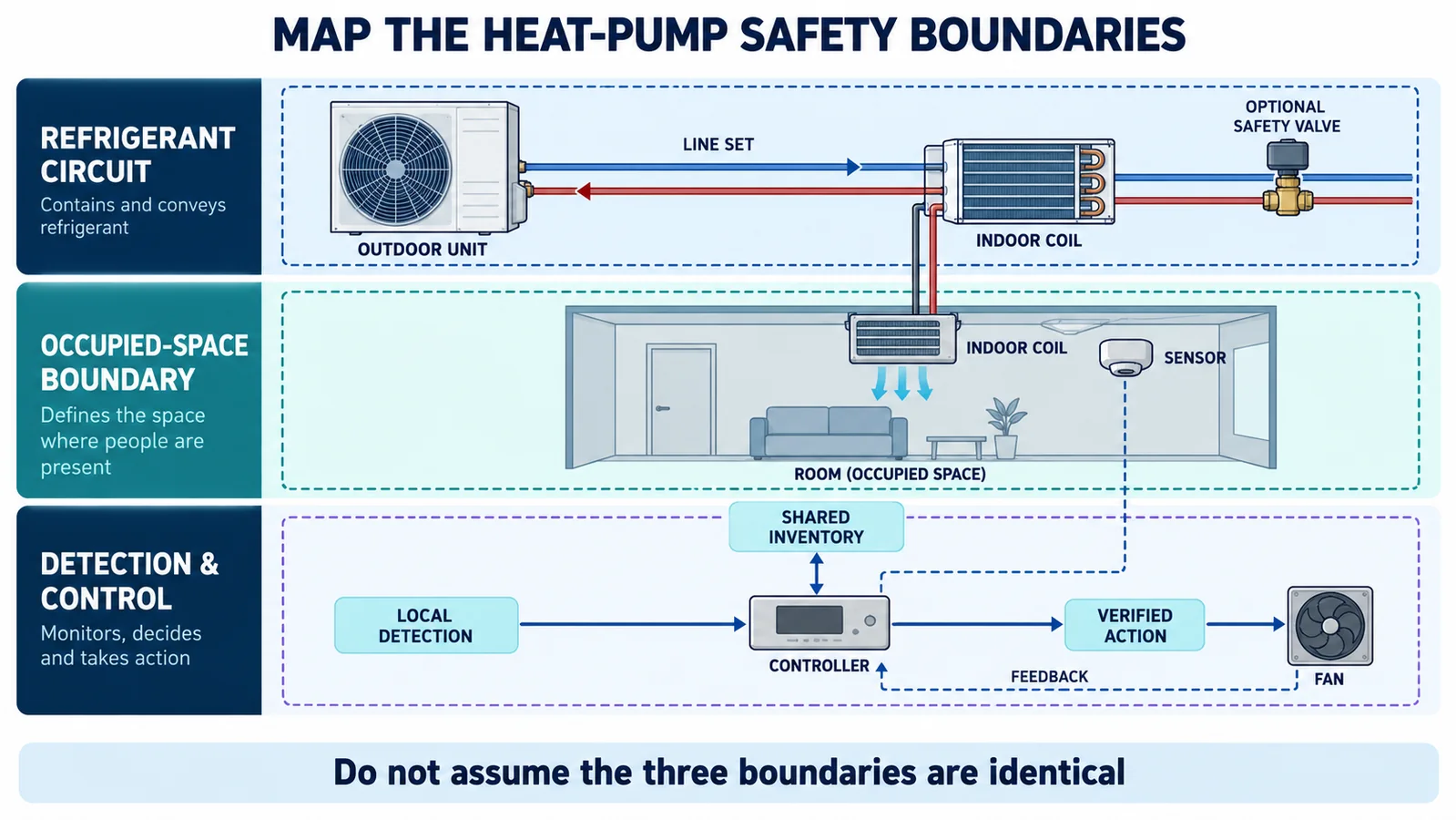
Gate 2: Map refrigerant, occupied-space, and control boundaries
Draw three layers. The refrigerant-circuit layer shows compressor, outdoor coil, line set, valves, indoor coil, distributors, joints, and the charge that can reach each segment. The occupied-space layer shows the room or duct system that can receive a release. The detection-and-control layer shows sensor, local controller, communication, power, actuators, feedback, and external interfaces.
The boundaries do not automatically coincide. A shared outdoor circuit can serve several rooms. A concealed air handler can discharge into multiple zones. A group controller can coordinate equipment but become unavailable during a network fault. The safety architecture must preserve which local space is affected and which actions remain available.
Use the boundary map to define responsibility. An integral equipment RDS and a separate room-monitoring system are not interchangeable unless the equipment certification explicitly recognizes that architecture. Likewise, a building automation alarm does not replace a local protective function merely because it receives the same data.
Gate 3: Identify every credible release source
Mark field joints, headers, distributors, return bends, service valves, branch connections, and other refrigerant-bearing components in the indoor assembly. For each source, record its orientation, release direction, adjacent surfaces, pressure state, and releasable inventory. Include sources outside the nominal coil compartment when the field line connection sits above a ceiling, in a closet, or behind a service panel.
The initial release may be a directional jet. It can cool the local mixture, entrain air, and impinge on metal or insulation before gravity and equipment airflow dominate. “Refrigerant is heavier than air” is therefore a screening observation, not a placement rule. Trace several plausible paths and test the candidates in production-intent geometry.
Group release points only when an engineering analysis establishes equivalence. Retain the reason why the selected test case is at least as challenging as the omitted ones. Every credible source should appear in the validation matrix or in a documented equivalence justification.
Gate 4: Select candidate zones from transport physics
A candidate sensing zone should intercept gas from the mapped sources in the required equipment states. Evaluate release momentum, forced airflow, natural convection, gravity, cabinet leakage, partitions, pans, insulation, filters, and nearby room boundaries. Avoid choosing a point only because it is mechanically convenient.
The installed sensor inlet matters more than the circuit board location. A cover, grille, membrane, bracket, shield, or pocket can delay transport. Specify inlet orientation and keep-clear volume in the drawing. Include tolerance stacks so insulation, wiring, or a service panel cannot close the path at production limits.
Use analysis and flow visualization to screen options, then confirm with controlled refrigerant releases and a reference concentration measurement. The test should distinguish transport delay from sensor/electronic delay. A candidate with strong bench response can fail when mounted behind a slow enclosure.
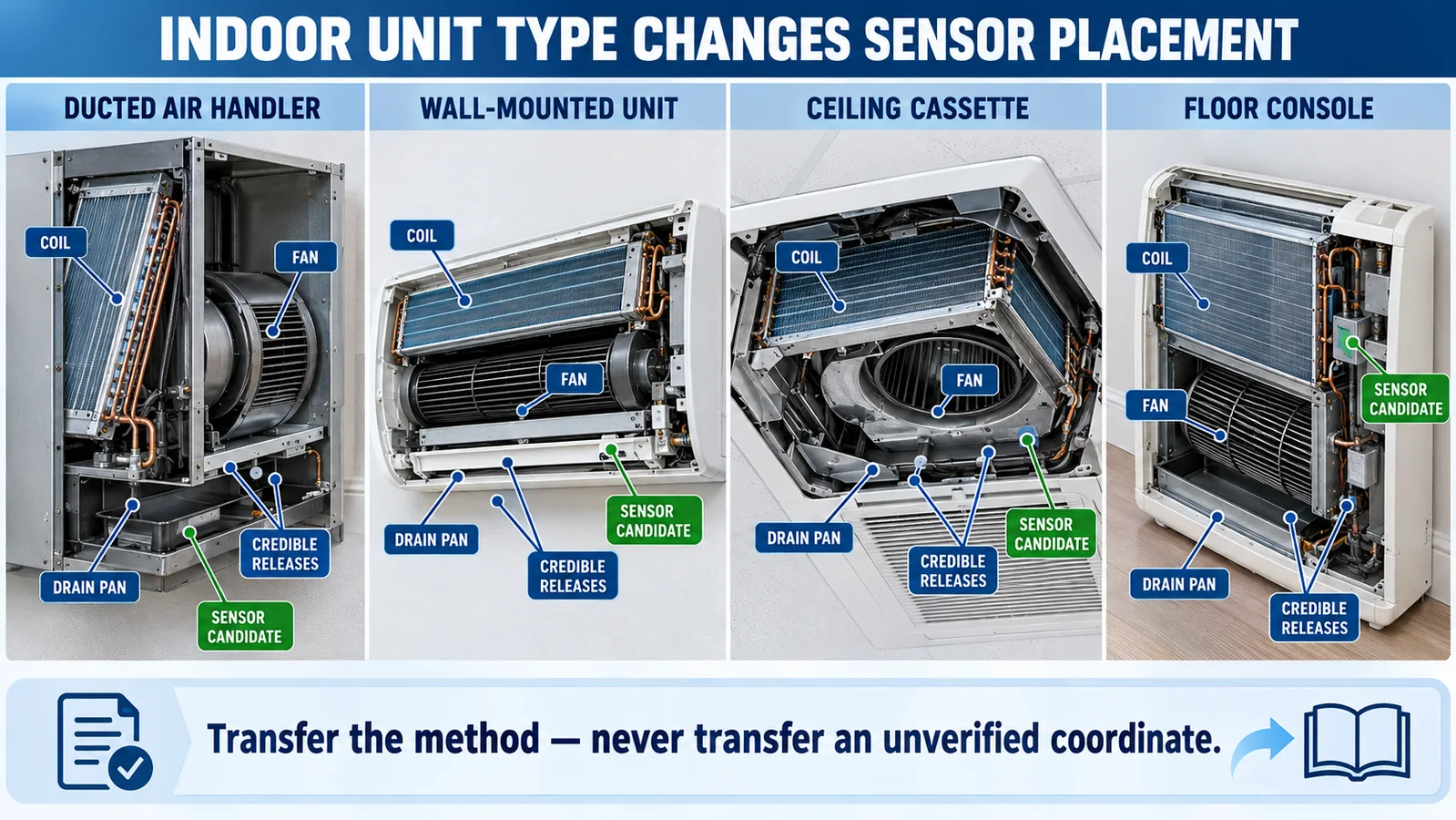
Gate 5: Treat each indoor-unit type as a separate geometry
Ducted air handlers, wall units, cassettes, and floor consoles route air differently. A ducted unit may use return-air mixing and zone dampers. A wall unit has a compact cross-flow fan and movable vane. A cassette uses a central fan, broad coil, drain pump, and multiple louvers. A floor console may form low internal pockets and discharge at different heights.
Transfer the engineering method, not a drawing coordinate. For every indoor type, remap release sources, low regions, fan states, drains, service access, and occupied-space openings. If a common sensor module is used across the family, each bracket and enclosure still needs equipment-specific evidence.
Product-family efficiency can come from reusable requirements, test fixtures, data formats, and control interfaces. It should not come from assuming that one successful placement applies to unrelated cabinets.
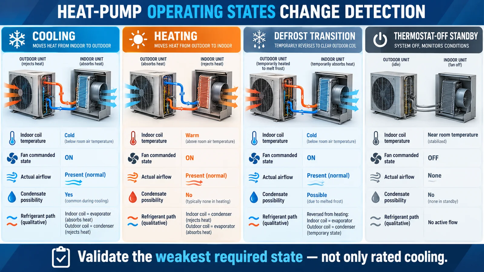
Gate 6: Validate cooling, heating, defrost, and standby states
Heat-pump mode changes the indoor coil temperature, refrigerant distribution, fan logic, airflow, water condition, and electrical-heat availability. During cooling the indoor coil produces condensate. During heating it is warm, and the fan may follow different startup logic. During defrost the outdoor unit changes state and the indoor fan or auxiliary heat may respond. During thermostat-off standby there may be no forced airflow at all.
Create a state table from the actual controller sequence. Record compressor and valve state, indoor fan command and verified status, auxiliary heat, dampers or louvers, coil condition, drain condition, and which refrigerant segments remain pressurized. Include transitions and faults that can persist long enough to affect detection.
Test the weakest required state rather than only rated cooling. Do not average results across modes. If the protective concept starts the fan after detection, the pre-alarm gas path and post-command dilution path are separate validation questions.
Gate 7: Include fan-off transport and failed-airflow cases
With the indoor fan stopped, gas can accumulate behind pans, in cabinet corners, below a coil, or near a field joint. Natural leakage to the room or duct may be slow. A location optimized for the running fan may be outside this stagnant path. Conversely, a low pocket that works in standby can be bypassed at high airflow.
Test fan off, low, nominal, and relevant high airflow. Include a dirty-filter or high-static condition when permitted by the product scope. Record actual airflow or feedback, not only the controller command. If a fan is expected to provide mitigation, evaluate failure to start, loss of feedback, and operation with closed zone dampers.
Decide how the controller handles this failure. A command without confirmation may be insufficient for the safety analysis. The required feedback and fallback action depend on the certified design, but the assumption must be explicit.
Gate 8: Map condensate, drain faults, and water exposure
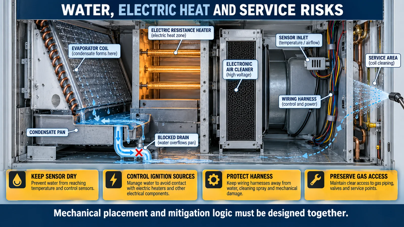
Cooling creates condensate, and heat-pump transitions can leave residual water during later modes. Map the normal path from coil to pan, trap, pump if present, and drain. Then map blocked-drain overflow, pan cracks, unit tilt, pump failure, carryover, cleaning, and harness wicking.
The detector needs gas access without being placed in normal splash or a credible overflow route. A water shield can help but may delay gas. Validate the production inlet, cover, and bracket under both gas and water conditions. Define whether wetting leads to continued operation, a detectable fault, recovery, or replacement.
After water testing, confirm the target-gas response remains within the equipment criteria. “No nuisance alarm” is not a complete pass if water blocks the inlet or damages the electronics.
Gate 9: Coordinate electric heat and other ignition-source controls
Ducted heat pumps can include electric resistance heat, electronic air cleaners, humidifiers, UV devices, or other accessories. The RDS mitigation concept may require de-energizing certain components when a leak is detected. The correct action is equipment-specific and should be derived from the applicable safety analysis and certification.
Map each accessory, power source, relay or communication path, default state, and feedback. Confirm that an optional kit cannot bypass the protective command. If the equipment uses a third-party thermostat or zoning panel, specify the required interface and behavior during alarm and fault conditions.
Mechanical placement and control logic must be developed together. A sensor located downstream of a heat source or isolated by a damper can create both response and mitigation problems. Validate the complete approved accessory set.
Gate 10: Define the sensor electrical interface
Document supply voltage and tolerance, current, connector, grounding, signal type, protocol, data rate, update behavior, warm-up, diagnostics, fault codes, and power-loss state for the exact sensor variant. If outputs can be customized, freeze the production suffix and controlled interface specification.
For analog signals, define valid range, out-of-range detection, open and short circuit behavior, ADC diagnostics, and reference integrity. For digital communication, define message integrity, address control, timeouts, stale-data detection, startup supervision, and recovery. A missing or invalid message must not appear as a healthy low concentration.
Evaluate EMC, cable routing, connector retention, condensation, and service handling in the equipment. Protect the harness from sharp edges, hot components, moving blowers, drains, and cleaning. End-of-line tests should detect missing, swapped, or incorrectly configured sensors.
Gate 11: Separate alarm, fault, and unavailable states
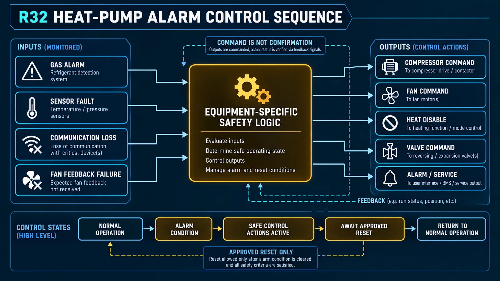
A gas alarm indicates that the detection criteria have been met. A sensor fault indicates that valid monitoring cannot be assured. Communication loss, power loss, warm-up, service mode, and controller restart may create additional states. The control design should not collapse them into one ambiguous bit.
Create a cause-and-effect table for each state. Define protective commands, annunciation, latching, event logging, permitted operation, and reset conditions. The system should fail safe according to the evaluated equipment concept. It should not automatically clear a gas event because a later communication fault hides the signal.
Keep local protection available when practical. A cloud service or building network can receive information, but the integral function should not depend on an unevaluated remote service. If a group controller is safety-relevant, its communication and power architecture belong in the certification evidence.
Gate 12: Write the mitigation sequence as commands plus feedback
Depending on the certified equipment, mitigation can involve indoor fan operation, compressor control, auxiliary-heat disable, damper commands, shutoff valves, ventilation, and audible or visible indication. Do not copy a generic sequence into every heat pump. Write the exact sequence for the model and applicable installation.
For each action, identify the command source, communication path, actuator, expected state, available feedback, timeout handling, and fallback. A compressor-stop command does not prove the compressor stopped. A fan-on command does not prove airflow. A valve-close command does not establish isolation unless valve position, leakage, residual charge, and fail state are addressed.
Test simultaneous events: gas alarm plus fan failure, sensor fault during mitigation, power interruption, controller reboot, and a second-zone alarm in multi-zone equipment. Preserve event order in logs where it supports diagnosis, without making timestamp synchronization a prerequisite for the protective response.
Gate 13: Budget end-to-end response time
The safety response includes release transport, passage through the sensor enclosure, sensing and filtering, communication, control decision, command transmission, actuator movement, and feedback. Component response time is only one part. Allocate a budget with margin for production and environmental variation.
Measure reference concentration at an appropriate point near the installed inlet while recording raw detector output, alarm state, control messages, commands, and physical actuator response. Avoid instrumentation that redirects the plume. Retain raw time histories, because a simple pass/fail record cannot explain where delay occurred.
Use the applicable standard and certification method for acceptance. Do not treat an illustrative timing allocation, a marketing response time, or a bench exposure as the equipment requirement.
Gate 14: Qualify production-intent equipment
Use released or production-representative coil, cabinet, pan, filter, insulation, wiring, covers, sensor housing, bracket, controller, and firmware. Include manufacturing tolerance extremes and approved alternate parts that can alter transport. Record unit serial or build identity and sensor lot.
Cross release sources with operating modes, fan states, orientations, drain conditions, accessories, ambient corners, alarm paths, faults, mitigation, and recovery. Repeat the limiting and most variable cases. If several configurations are grouped, document the equivalence rationale.
The qualification report should include setup drawings, photos, reference and sensor traces, control logs, acceptance criteria, results, deviations, and released revisions. Keep the report connected to the product configuration database.
Gate 15: Design production and end-of-line checks
Production cannot recreate the entire release test, but it can verify that the qualified configuration was built. Check sensor part and suffix, bracket, fastener, inlet direction, keep-clear region, connector lock, harness routing, controller recognition, address, diagnostics, and an approved functional path.
Use fixtures, barcode control, keyed connectors, or machine vision where they reduce assembly error. Prevent software from accepting an unsupported sensor or indoor-unit combination. Record the result for traceability.
Distinguish electrical simulation from gas-function verification. Each proves different parts of the chain. The production control plan should state exactly what is tested and what remains covered by design qualification and supplier controls.
Gate 16: Make commissioning and service configuration-safe
Installation instructions should show the exact sensor position for every permitted orientation and field option. Commissioning verifies physical installation, wiring, controller mapping, fan or louver behavior, fault reporting, and the manufacturer-approved functional test. Do not instruct installers to create an uncontrolled refrigerant release.
Service replacement must restore the qualified part, bracket, inlet orientation, harness, address, and firmware compatibility. If a sensor stores calibration or identity data, define replacement and pairing. Require a functional check after replacement and record the unit and sensor revision.
Provide troubleshooting that separates refrigerant alarm, sensor fault, wiring fault, water exposure, and controller fault. Never encourage bypassing or masking the detector to keep equipment running.
Gate 17: Control platform and software changes
Changes to coil geometry, fan curves, pans, insulation, cabinet seams, filters, heaters, valves, charge limits, sensor hardware, protection covers, signal filtering, communication, or mitigation logic can affect the safety case. Route them through a documented impact review.
Use focused retesting only when evidence shows which cases remain limiting and why the change cannot create a new path. Update drawings, bill of material, firmware, production checks, instructions, and service parts together. Field evidence should feed the same process.
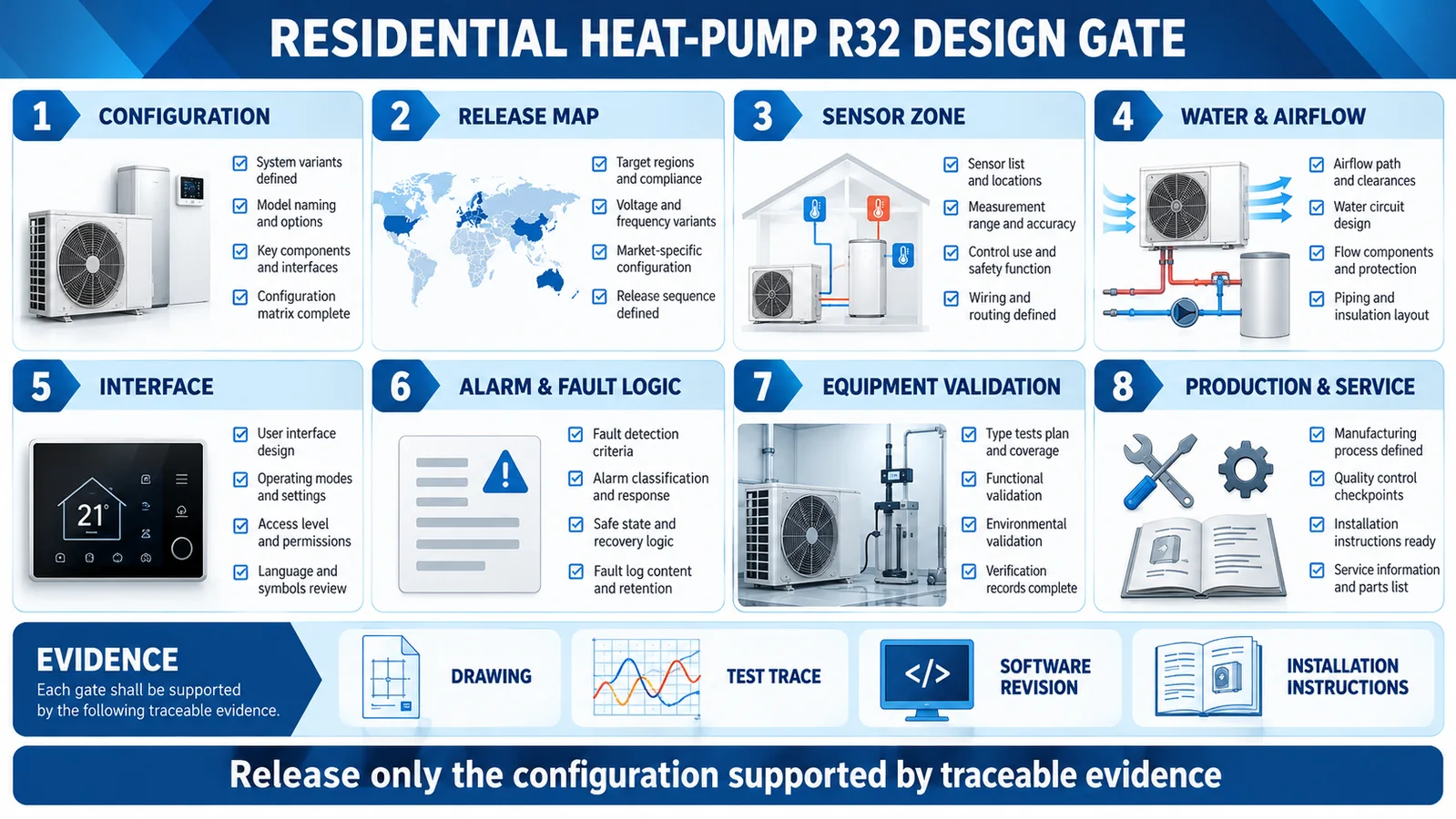
The design-gate graphic below can serve as a release-review structure. Each gate should point to controlled evidence rather than a verbal assurance.
Gate 18: Define the compliance evidence package
An engineering design review should produce more than a pass/fail slide. Assemble a controlled evidence package containing the configuration matrix, circuit and occupied-space boundaries, release-source map, candidate-zone rationale, test plan, calibrated instrumentation records, raw concentration and timing traces, software and firmware revisions, photos of the exact installation, and deviations with technical disposition.
Link each requirement to one or more objective records. If several heat-pump models share evidence, document why their charge, coil layout, enclosure, fan curve, detector path and mitigation sequence are equivalent or less challenging. Marketing family names are not an engineering equivalence argument.
Record uncertainty and repeatability. A single passing release close to the limit may not provide adequate production margin. Repeat limiting cases and include assembly tolerances, voltage, temperature and airflow corners that could slow detection or action. Preserve failed trials as well as successful ones; they explain design changes and prevent future teams from returning to rejected locations.
Gate 19: Review installation interactions outside the indoor unit
Residential installations add return grilles, ducts, closets, drain traps, line-set penetrations, insulation and field wiring that can change the qualified condition. Define which installation features are part of the safety case and which variations are permitted. A ducted air handler tested with an open return should not automatically cover a tightly sealed closet or a long return path if those features change gas transport.
Review condensate routing, auxiliary pans and float switches. Field-applied foam or mastic must not cover the detector inlet or required cabinet openings. Line-voltage and communication wiring should maintain required separation and grounding, while harness length and connector choices stay within the validated electrical design.
Installation instructions should include clear drawings, prohibited zones and an inspection checklist. If orientation conversion is allowed, specify which bracket, harness path, drain pan and software setting change with the orientation. Commissioning should verify the actual installed configuration against the model record rather than relying on a generic startup screen.
Gate 20: Plan the service life and replacement path
Define the expected detector maintenance or replacement policy using controlled product and equipment requirements. Consider dust, condensate history, cleaning chemicals, temperature cycling, power transients and long standby periods. The service plan should say which electronic self-tests are available, what they do not prove, and when an approved functional challenge or replacement is required.
The replacement part must preserve refrigerant calibration, interface, diagnostic semantics, response behavior and mounting geometry. If a new module is introduced, do not treat connector compatibility as qualification. Run the change-control analysis and required regression tests. Keep event logs and replaced-part information so field experience can improve the next design revision.
Gate 21: Close the review with accountable owners
Assign every open item to a named engineering function: refrigeration, airflow, electrical, embedded software, controls, compliance, manufacturing, service or supplier quality. Record the evidence needed, due date and release impact. A detector issue should not remain between disciplines because one team owns the module while another owns the final response.
The final review should confirm that drawings, firmware, controller parameters, production checks, installation instructions and service parts describe the same configuration. Resolve discrepancies before approval. A technically sound test cannot protect a product whose released bill of material or software differs from the tested unit.
After launch, review alarm, fault, replacement and no-fault-found data at defined intervals. Compare field configurations with the qualification matrix and feed credible new cases into change control. This closes the loop between laboratory evidence and actual residential heat-pump operation.
Product integration example: ZRT512C-A
Winsen’s ZRT512C-A is listed in the verified WooCommerce export as an NDIR refrigerant detection module for R32, R454B, and R290, with PWM, RS485, and UART output options listed. Its official image is shared by several product variants, so the exact suffix and controlled datasheet must be confirmed.

Product data can support candidate selection, but it does not approve a heat-pump location or control sequence. The OEM must integrate the exact module into the released indoor unit and validate the full RDS.
Související průvodci zahrnují Umístění senzoru R32 v klimatizačních jednotkách, furnace-and-coil integration, Řídicí sekvence alarmu úniku R32, a equipment-orientation sensor placement.
What to send for a residential heat-pump review
Provide refrigerant and maximum charge, outdoor and indoor models, circuit and cabinet drawings, occupied-space assumptions, installation orientations, credible release map, fan and accessory states, drain design, proposed sensor zones, interface specification, alarm and fault logic, mitigation architecture, annual volume, and certification market.
Winsen can review candidate sensing interfaces and help structure the design-gate and validation matrix before hardware and software are frozen.
Contact Winsen for an R32 heat-pump detection review.
Reference
- UL Solutions: Kontrola systémů detekce chladiva v zařízení HVAC
- UL Solutions: Aktualizované požadavky na systémy detekce chladiva
- Řešení UL: Odezva senzoru v systémech HVAC
- AHRI Iniciativa pro výzkum hořlavých chladiv
- AHRTI 9009: Detekce úniku chladiv A2L v zařízení HVACR
- Daikin R32 residential heat-pump documentation center
- Winsen ZRT512C-A product page
