
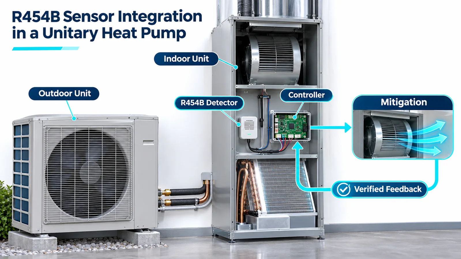
A unitary heat pump reverses the refrigerant cycle, changes coil roles, moves air through indoor and outdoor sections, and passes through standby, heating, cooling and defrost states. An R454B detector must remain meaningful across those states. The integration is therefore not a sensor added to a wiring diagram; it is a system function spanning refrigerant inventory, gas transport, electrical interfaces, controller priorities, actuators, production and qualification.
Strong R454B heat pump sensor integration begins by defining the equipment boundary and credible releases, then validating the complete chain from gas arrival to physical mitigation. The detector supplier can characterize a module. The heat-pump OEM must prove that the installed location, controller and hardware achieve the released safety design.
This guide describes a design method. It does not prescribe a universal threshold, location, detector count or control sequence. Follow the current applicable equipment requirements, controlled refrigerant properties, certification program and exact detector documentation for the target product and market.
1. Define the Heat-Pump System Boundary
Start with the product architecture. A unitary heat pump may be packaged or split; ducted or ductless; indoor, outdoor or mixed; single- or multi-zone. Define which refrigerant-containing components and occupied-space paths are inside the detection function.
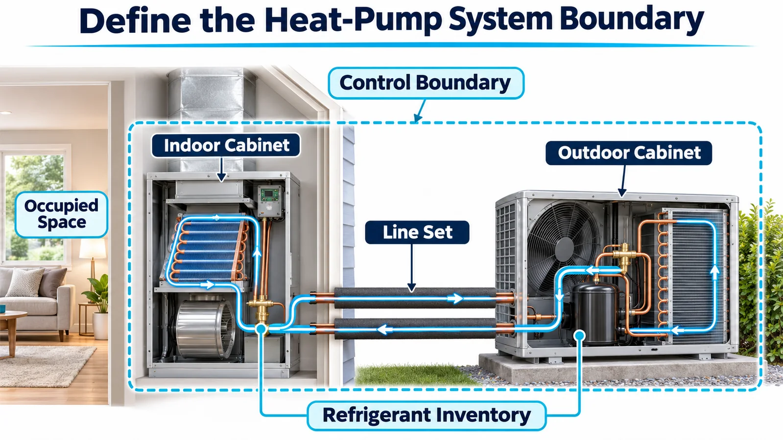
Record maximum charge for every approved indoor/outdoor combination, line-set limits, factory and field joints, accessories, orientations and installation environments. Identify the controller with final authority and any thermostat, zone panel, building system or outdoor board that participates.
The boundary should include power and communication. If the detector is powered by the indoor board but mitigation requires the outdoor compressor contactor, define behavior when the interunit link fails. If a packaged unit has separated indoor and outdoor compartments, document whether bulkheads are gas barriers or exchange paths.
Write the intended safety function in plain language: detect the covered release, produce valid alarm/fault information, transition the controller to a defined state, command required equipment actions, verify critical actions and hold/recover according to controlled rules.
2. Map Refrigerant Inventory and Release Sources
Overlay the refrigerant schematic on the physical unit. Mark indoor coil, outdoor coil, compressor, accumulator, reversing valve, expansion devices, distributors, headers, return bends, service valves, transducers, joints and field connections. Identify which sources are inside the occupied-air path.
Group sources by compartment, initial release direction and operating state. A discharge-side leak in cooling can differ from the same physical joint in heating because pressures, temperatures and flow paths change. A reversing-valve or compressor-bay release may be outdoor-dispersed in one enclosure but communicate through penetrations in another.
Use the map to choose validation points and candidate detector zones. Preserve it under change control. Coil, line-set, valve, insulation or cabinet changes can alter transport without changing the marketing model.
Do not assume every release needs identical mitigation or that outdoor dispersion eliminates analysis. Document why each credible source is covered, excluded or handled by another measure.
3. Separate Indoor and Outdoor Compartment Functions
The indoor section often connects directly to occupied air; the outdoor section usually disperses to ambient. Packaged equipment may place both inside one chassis with bulkheads, drains and wire penetrations. Split systems add field piping and communication dependencies.
For each boundary, determine gas exchange under fan-off, fan-on, wind and pressure conditions. Test seams, grommets, tube openings and drain paths. If one indoor detector is expected to cover a neighboring section, prove the minimum exchange path. If a partition is credited with isolation, prove it across production tolerance.
Avoid routing gas toward electronics simply because the controller is nearby. Detector location should balance representative exposure with water, temperature, vibration, electrical and service constraints.
The controller architecture should remain clear: which detector protects which volume and refrigerant circuit, which board validates data, and which board commands physical actions.
4. Build an Operating-State Map
Heat pumps have more states than “on” and “off.” Map standby, cooling startup, steady cooling, cooling shutdown, heating startup, steady heating, defrost entry, defrost, defrost exit, fan delay, auxiliary heat and fault modes.
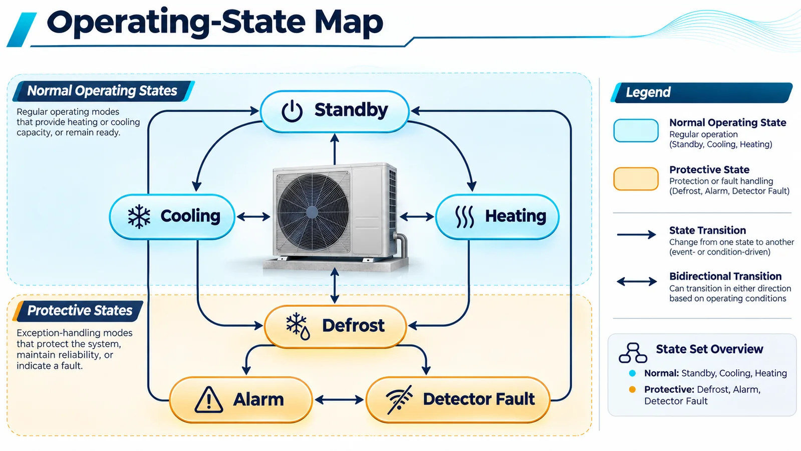
For each state, record refrigerant direction, active coil roles, fan states/speeds, valve position, hot/cold surfaces, likely compartment pressure and available mitigation authority. A detector near the indoor coil may see different transport during cooling and heating. Defrost can stop or reverse fans and create rapid temperature/moisture transitions.
Include transition states. A release may begin just before compressor shutdown, while the blower runs down or while the reversing valve changes. Controller logic should not lose alarm priority because normal state logic is between modes.
Use the state map to define tests and software requirements. It also helps service teams interpret logs: the same sensor signal may arrive under different airflow and thermal conditions.
5. Choose Sensor Locations From Coverage Evidence
Candidate locations should provide representative exposure from covered release sources across the state map, while meeting inlet clearance, environment, drainage, vibration, harness and service requirements. Height alone is not a design method.
Build a coverage matrix by release source, operating state, orientation and candidate detector. Mark direct, indirect, uncertain and no coverage. Analyze uncertainty with airflow visualization/CFD, then verify limiting cases on production-intent hardware.
Consider detector count by independent gas zones. Multiple coils, bulkheads or orientations may need separate sensing. One well-mixed volume may not. Include detector-failure effects: another sensor is not redundant unless its coverage and control logic are validated.
Document location using stable datums, inlet orientation and keep-out volumes. Protect from condensate and spray without enclosing the gas path. Ensure heating or defrost temperatures remain inside the characterized detector envelope.
6. Specify the Electrical and Data Interface
The interface contract should define exact R454B variant, supply, transient behavior, startup/warm-up, validity, measurement/alarm output, units, update timing, diagnostics, timeout, checksum or plausibility checks, fault codes and recovery.
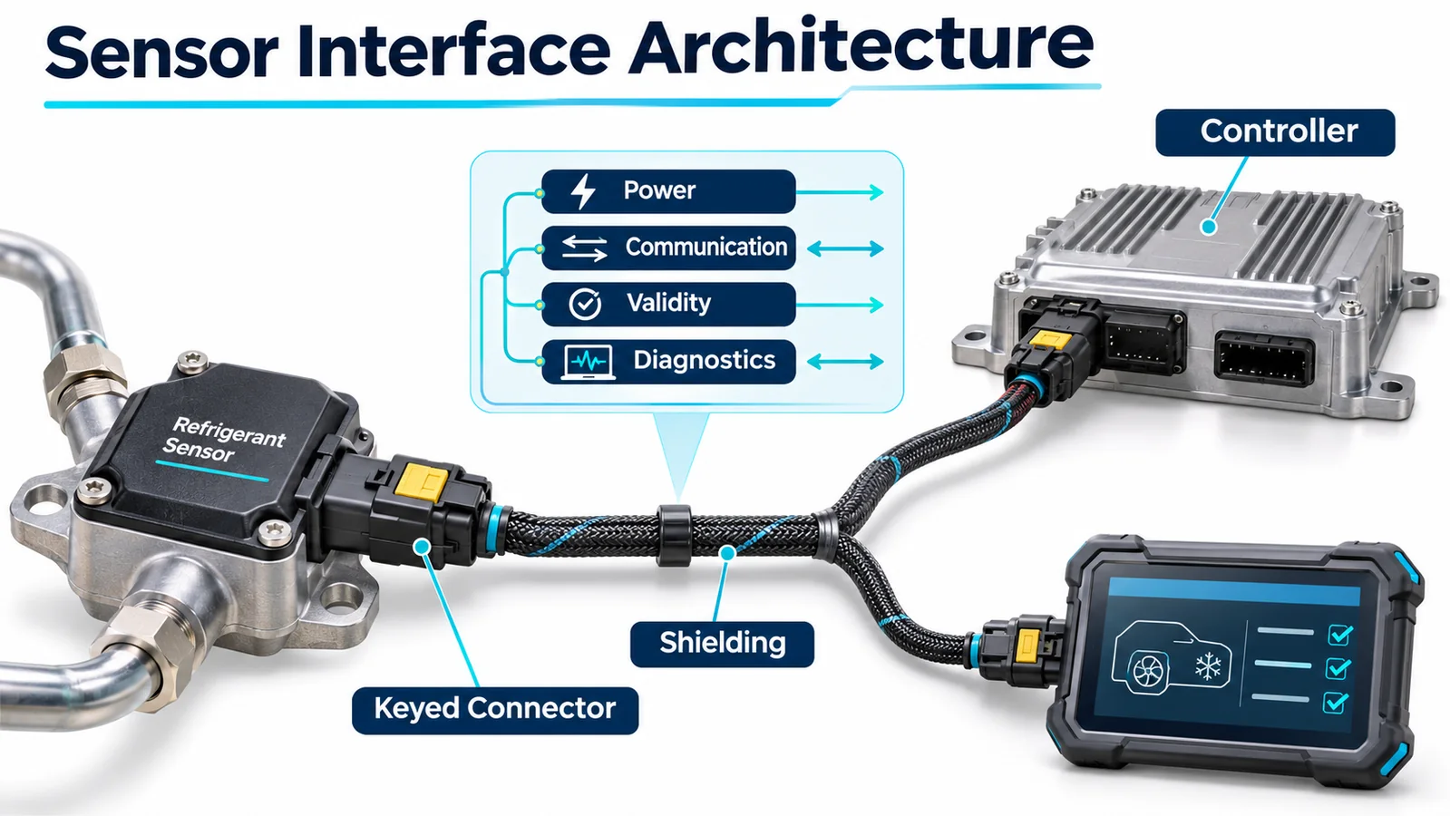
Treat warm-up, invalid and stale data as explicit states. A repeated zero after communication freezes is not clean air. For analog channels, detect open/short/out-of-range behavior. For digital channels, test bad frames, duplicate addresses, frozen counters and delayed messages.
If concentration and alarm outputs both exist, assign decision ownership and disagreement behavior. Avoid uncontrolled thresholds in multiple layers. Carry gas identity and units with the configuration.
Analyze grounding, EMC, cable routing and power domains. The detector should not reset unnoticed when compressors, heaters or contactors switch. Test brownout and one-sided power loss between indoor and outdoor electronics.
7. Create Alarm and Fault State Machines
Separate valid refrigerant alarm, detector diagnostic fault, communication fault, stale data, controller fault and mitigation-device fault. They may share protective actions, but their meaning, annunciation, logs and recovery differ.
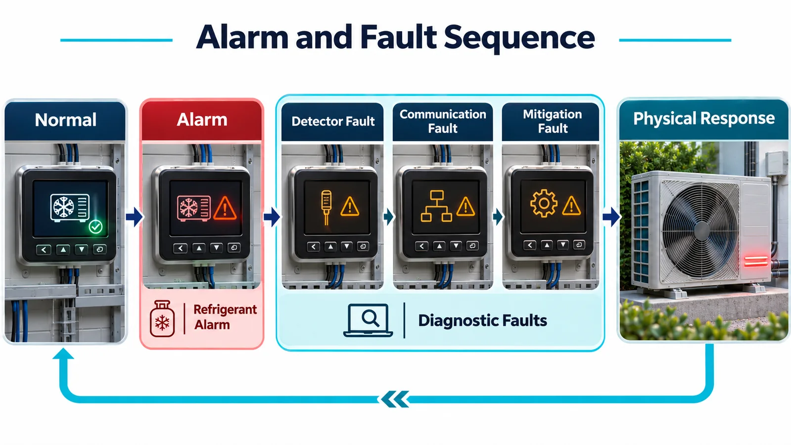
Build a state table covering startup, normal, alarm, fault, power interruption, service/test and recovery in every operating mode. Define compressor, indoor blower, outdoor fan, reversing valve, auxiliary heat, zoning/dampers, alarms and remote signals according to the released safety design.
Safety priority must override comfort and defrost requests when required. The system should not re-energize a compressor or heater because a normal-mode transition runs after the alarm task. Use centralized state ownership and test race conditions.
Define latching and reset. Require the released valid-data and actuator conditions before normal operation returns. Protect service overrides and ensure they cannot persist silently.
8. Coordinate Indoor and Outdoor Controllers
Split heat pumps commonly divide control between indoor and outdoor boards. Define which board owns detector validity and safety state, how state is transmitted and what each side does when communication fails.
Do not rely on a cloud, thermostat or building network for a local time-critical response unless the architecture and fault tolerance explicitly support it. Local equipment should transition deterministically when external communications are lost.
Include message freshness, sequence and acknowledgement. A board should not continue using an old “normal” state after the link fails. If the compressor contactor or drive is outdoor, the outdoor board must receive and act on a valid command and provide appropriate feedback.
Simultaneous events need priority: defrost request plus alarm, sensor fault during alarm, power cycle during mitigation, or heat demand during communication loss. Test them on production firmware and communication hardware.
9. Verify Physical Mitigation, Not Only Commands
Identify required physical outcomes: compressor de-energized, blower/fan state achieved, electric heat de-energized, valve position controlled, dampers open/closed and annunciation active as designed. Choose feedback that actually demonstrates those outcomes.
Auxiliary contacts, drive status, current, fan speed, airflow/pressure, heat contactor feedback and valve position can provide evidence, each with limitations. A software command echo is not actuator feedback.
Inject stuck relays, welded contacts, failed motors, blocked dampers and contradictory feedback. Define the mitigation-fault state and remote/service messages. Preserve the primary safe commands while avoiding repeated cycling that obscures failure.
Synchronize detector, controller and actuator timestamps in tests. System response budgets include gas transport and physical action, not only detector response.
10. Address Heating and Defrost Environments
Heating can place the indoor detector near a warm coil and auxiliary heat; cooling can create condensate; defrost can cause rapid reversals and moisture. Validate temperature/humidity transitions at the actual bracket, not only room ambient.
Keep the inlet out of direct water and drain overflow. Use open splash protection and cable drip loops. Test freeze/thaw where applicable. After environmental exposure, repeat diagnostics and gas response.
Evaluate cleaning chemicals, insulation/adhesive vapors and service exposures. Cross-response or slow recovery can cause nuisance alarms or hidden sensitivity loss. Use the supplier’s controlled restrictions and the OEM’s approved chemical list.
If the controller suppresses signals during a known transient, prove that a real leak remains detected and that suppression is bounded and controlled. A broad “defrost inhibit” can create an unmonitored interval.
11. Integrate the ZRT512C-A Conservatively
Winsen lists the ZRT512C-A as an NDIR refrigerant detection module family option for R454B, R32 and R290 applications, with controller-oriented outputs in current product information. Exact gas calibration, supply, protocol, range, response, diagnostics, mechanical details, environmental limits and qualification evidence must be confirmed from current controlled project documents.

Request the full model code and calibration, mechanical drawing and inlet restrictions, connector/pinout, power transient behavior, startup and validity states, alarm/fault semantics, communication timing, environmental/condensation limits, life/drift evidence and change-notification process.
A family capable of multiple gas variants does not imply automatic gas identification. The installed module and controller configuration must agree on R454B. Use part and electronic identity controls.
The heat-pump OEM must validate installed exposure, operating-state response, control logic, actuator feedback, production and equipment-level requirements. A component module alone does not establish compliance.
12. Design Manufacturing Controls With the Product
Production must preserve sensor variant, bracket location/orientation, inlet clearance, harness route, connector engagement and software configuration. Use keyed parts, stable datums, fixtures and electronic identity checks.

End-of-line tests should verify communication, gas identity, diagnostics, alarm/fault state handling and critical outputs. Define controlled functional exposure or audit testing where required. Internal self-test does not prove gas transport or location.
Link unit serial, detector part/revision, controller firmware/configuration and test result. Prevent mixed indoor/outdoor software combinations outside the compatibility matrix.
Audit the physical keep-out around the inlet. Foam, wire, sealant and labels can defeat a qualified location without affecting electrical tests.
13. Build a Heat-Pump Qualification Matrix
Include:
| Factor | Nivells representatius |
|---|---|
| Font d'alliberament | indoor coil/joints, outdoor circuit sources and boundary cases |
| Mode | standby, cooling, heating, defrost and transitions |
| Flux d'aire | indoor/outdoor fan states, speeds, delays and faults |
| Configuració | cabinet, coil, orientation, heat kit, duct and line-set variants |
| Medi ambient | temperature, humidity, condensate, wind and relevant wet/freeze cases |
| Detector | location tolerance, production revision and aged/conditioned samples |
| Controls | alarm, detector fault, stale data, interboard loss and power interruption |
| Actuators | stuck contactor, fan failure, heat/valve/damper feedback and recovery |
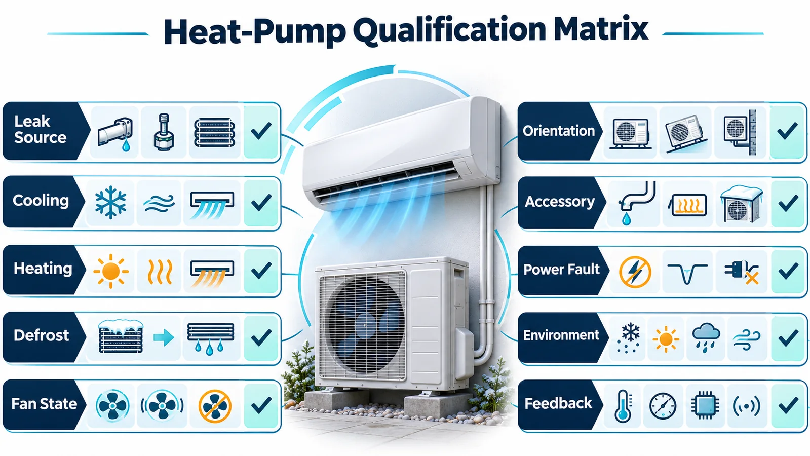
Define release method and acceptance before tests. Capture detector output, controller states, communications, commands, actuator feedback and local concentration measurements with synchronized time.
Use production-intent panels, seals, brackets, harnesses, boards, firmware and accessories. Repeat limiting cases and preserve configuration/revision evidence.
14. Plan Service and Field Replacement
Service tasks can move the detector or harness during coil, blower, heat and drain work. Define protection, removal and post-service verification for each task. Temporary inlet covers must be removed visibly.
Replacement modules must match R454B calibration and electrical/protocol revision. Key parts and verify identity. Restore the exact bracket and route and run the released diagnostic/functional checks after panel closure.
If controller or outdoor board is replaced, confirm software compatibility and safety configuration. Do not rely on default parameters. Record the change with equipment serial and test result.
Returned-part analysis should preserve field context—logs, orientation, installation photographs, contaminants and service history—rather than judging only a cleaned bench result.
15. Llista de verificació de llançament d'enginyeria
Confirmeu que:
- The equipment boundary, R454B inventory and approved combinations are controlled.
- Credible release sources map to detector coverage.
- Indoor/outdoor compartment exchange assumptions are validated.
- Cooling, heating, defrost, standby and transitions are represented.
- Location and detector count follow transport evidence.
- Interface defines gas, unit, validity, alarm, fault, stale data and recovery.
- Indoor/outdoor controller loss has deterministic behavior.
- Safety state overrides comfort, defrost and service requests.
- Critical commands use suitable physical feedback.
- Heat, condensate, freeze, cleaning and electrical environment are covered.
- Les afirmacions de producte es basen en proves controlades actuals.
- Manufacturing prevents wrong variant, position and configuration.
- Qualification uses production-intent hardware/software and repeats limiting cases.
- Service returns the equipment to the qualified state.
16. Review Margin and Change Control
Compare qualification cases to find the slowest gas arrival, lowest exposure, longest processing and slowest physical action. Probe sensitivity to location tolerance, fan performance, cabinet leakage, line-set configuration and environmental conditions. Improve fragile mechanisms rather than relying on a narrow pass.
Define regression triggers for coils, compressor, reversing valve, circuit routing, cabinet, fans, heat kits, detector, bracket, harness, boards, communication, firmware and thresholds. Link each trigger to analysis and limiting tests.
Maintain a compatibility matrix across sensor, indoor board, outdoor board, thermostat/zone interface and software. Manufacturing and service tools should reject unsupported combinations.
Field alarms, faults and replacements should feed engineering review. Patterns can reveal water paths, service movement, software mismatch or transport assumptions before they become widespread.
17. Commission the Complete Detection-to-Mitigation Chain
Commissioning should prove that the installed unit still behaves like the qualified design. A successful detector self-test or a plausible concentration value proves only a portion of the chain. The commissioning procedure should confirm sensor identity, approved firmware and configuration, connector engagement, communication health, expected controller state, commanded outputs, feedback inputs and restoration behavior. The result should be captured in a form that can be associated with the equipment serial number and software versions.
Start with non-gas checks where the released design provides them. Verify that disconnecting the detector, interrupting its communication or invoking an approved diagnostic mode produces the specified fault state rather than a normal reading. Confirm that the indoor and outdoor controls agree on detector health and that the user or service interface identifies the condition without confusing it with a refrigerant alarm. A fault that silently disables cooling or heating may be noticed by the occupant, but it is not an adequate substitute for a defined diagnostic.
Then test the commanded mitigation path using the OEM’s approved method. Observe the physical outcome rather than stopping at a relay bit or network message. If the response depends on airflow, confirm the correct fan operates and that dampers, zoning devices or accessories do not defeat the intended path. If a compressor, heater, valve or contactor must change state, verify that the device actually reaches that state and that available feedback agrees. Record the time sequence at a resolution adequate to identify communication delay, software persistence, actuator delay and airflow establishment.
Heat pumps require commissioning in more than one operating condition. A response verified during cooling does not automatically prove behavior during heating, defrost, standby, thermostat transition or loss of communication between indoor and outdoor units. The released procedure should identify which states require direct checks and which are covered by controlled analysis. It should also define safe test prerequisites, permitted service tools and any temporary overrides that must be removed before handover.
Do not improvise by releasing refrigerant into occupied space or by using an unapproved test gas. The detector supplier and equipment manufacturer should define the permitted stimulus, concentration range, application method and acceptance criteria. An unsafe or chemically inappropriate field test can create exposure, contaminate the sensing element or produce a result that has no relationship to the certified configuration.
18. Design Diagnostics for Engineers and Service Technicians
Useful diagnostics separate four questions: Is the detector alive? Is its measurement valid? Has the configured alarm condition been reached? Did the equipment perform the required action? Collapsing these into one generic code makes root-cause analysis slow and encourages unnecessary sensor replacement. A service interface should expose enough context to distinguish a detector fault, wiring or communication fault, configuration mismatch, refrigerant alarm and mitigation feedback failure.
For a digital interface, consider retaining gas identity or calibration identity, measurement and unit when permitted, validity, alarm state, fault category, configuration/version information and a monotonic message or freshness indicator. The equipment controller should timestamp transitions and record the operating state, relevant fan/valve/compressor commands and available feedback. A frozen value that remains numerically plausible must not be accepted indefinitely merely because it lies below the alarm threshold.
Diagnostic logs need engineering discipline. Define retention depth, power-loss behavior, clock limitations and access control. Avoid presenting uncertain field data as laboratory-grade concentration history. The primary purpose is to reconstruct state transitions and configuration, not to turn an HVAC control into an exposure-monitoring instrument. Documentation should explain the meaning and limitations of every service value.
Replacement workflows should be deliberate. The service tool or controller should detect an unsupported detector, calibration family or firmware combination where technically feasible. After replacement, require the specified initialization, health check and mitigation-path verification. If configuration is stored in the equipment controller, confirm that it cannot apply an R454B setting to an incompatible sensor. If configuration resides in the detector, confirm that the controller reads and validates it rather than assuming compatibility from connector shape.
Finally, aggregate field evidence by equipment configuration, not only by sensor part number. Repeated water faults in one cabinet orientation, communication faults with one board revision or alarms linked to one airflow accessory can reveal system-level weaknesses. A closed-loop review connects field data to design changes, regression testing, supplier controls, service bulletins and manufacturing containment while preserving traceability to the released heat-pump configuration.
Service documentation should mirror this diagnostic structure. Give technicians a decision tree that begins with the reported state and observable feedback, then directs them to connector, power, communication, configuration, airflow and actuator checks before replacement. Identify which procedures are diagnostic-only and which are part of the released protective-function verification. Require the cabinet, insulation and drain components to be restored exactly as qualified after access. A detector that passes on the bench but repeatedly faults in one installed location points to an integration issue, not necessarily a defective sensing element. Clear documentation reduces indiscriminate part swapping and preserves evidence that engineering needs for corrective action.
Remote diagnostics require the same controls. Authenticate access, restrict commands that could alter safety-related configuration, log changes and ensure that loss of connectivity cannot leave a temporary override active. Display the equipment model, detector identity and software versions together so support personnel can confirm compatibility before interpreting data. Where a remote tool cannot prove physical fan or valve feedback, it should say so explicitly and direct an on-site check rather than presenting a commanded state as verified mitigation.
Conclusió
R454B sensor integration in a unitary heat pump is a full-system engineering task. Reversing operation, distributed controls, water, heat and operating transitions determine whether a detector can support the intended response. A robust design validates the chain from credible release to confirmed physical mitigation and preserves it through production and service.
For an engineering review, provide refrigerant/charge, architecture and approved combinations, refrigerant schematic, operating-state map, candidate locations, interface/protocol, alarm/fault sequence, feedback, environment, annual volume and target certification market.
Referències
- Solucions UL: inspecció de sistemes de detecció de refrigerants en equips de climatització
- Solucions UL — Requisits actualitzats per als sistemes de detecció de refrigerants
- Solucions UL — Resposta del sensor en sistemes HVAC
- AHRI — Iniciativa de recerca de refrigerants inflamables
- AHRTI 9009 — Detecció de fuites de refrigerants A2L en equips HVACR
- Copeland — Solucions de producte A2L
- Winsen — ZRT512C-A Refrigerant Detection Module
