
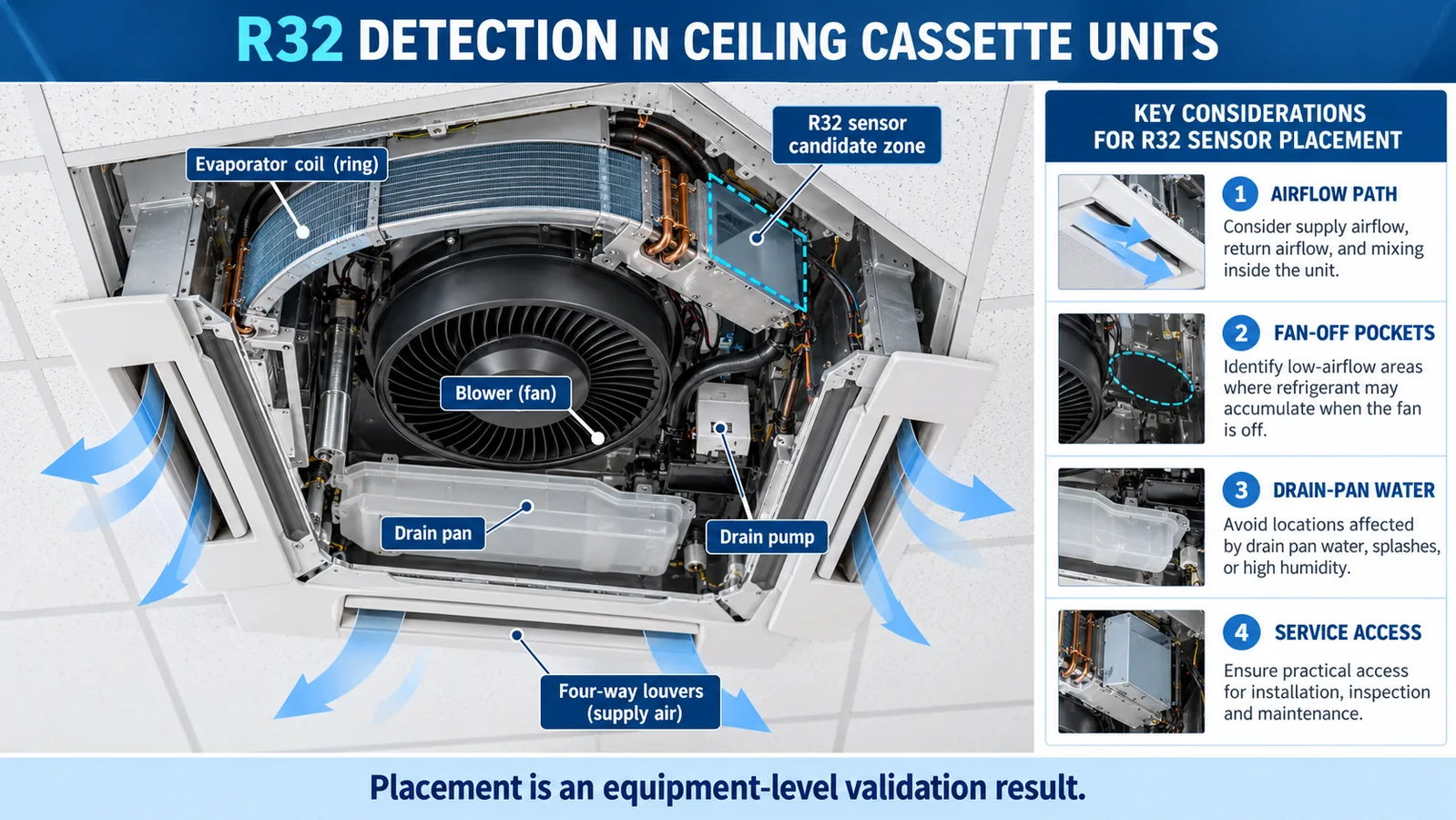
Ceiling cassette air conditioners create a distinctive refrigerant-detection problem. The indoor unit is installed above or within a suspended ceiling, the evaporator coil surrounds a central fan, conditioned air leaves through several independently configurable louvers, and condensate is collected and pumped from a shallow drain pan. A sensor that looks well positioned on a drawing can be bypassed by four-way airflow, exposed to water, hidden behind insulation, or left in a stagnant pocket when the fan stops.
This guide explains how an OEM engineering team can develop and validate an R32 sensor for a ceiling cassette. It focuses on the relationship between credible release sources, fan and louver states, the ceiling void, the occupied room, drain-pan water, harness routing, controls, commissioning, and change management. It does not prescribe a universal mounting point, alarm threshold, or mitigation sequence. The final design must follow the applicable equipment certification, current standard requirements, and the manufacturer’s controlled instructions.
Why a ceiling cassette needs its own placement study
A cassette is not simply a wall unit turned horizontal. Its refrigerant circuit is distributed around a broad coil, its air inlet is usually central, and its discharge paths are split among two, three, or four sides. The unit may sit partly above the room boundary, with openings into both the occupied space and the ceiling void. These geometric features create several possible routes from a leak to a detector.
The relevant route also changes with operating state. During cooling, the fan can entrain and transport a release through the coil and discharge louvers. During standby, gravity, thermal differences, leakage through panel gaps, and the volume of the ceiling recess may dominate. A field-configured louver can close one discharge side, while an optional fresh-air or branch-duct connection can create another path. Because these states are equipment-specific, a location proven in a wall-mounted indoor unit cannot be transferred to a cassette without evidence.
Start the project by defining every cassette variant covered by the design: cabinet size, coil arrangement, fan and motor, decoration panel, louver options, drain-pump configuration, branch connection, refrigerant charge, controller version, and permitted installation. The sensor location must be traceable to that configuration.
Separate the cabinet, ceiling void, and occupied-space boundaries
Create a section drawing that distinguishes three volumes. The first is the cassette cabinet and internal air path. The second is the ceiling void or recess around the cabinet. The third is the occupied room below the decoration panel. Do not assume that a visible gap provides rapid gas exchange between them. Insulation, gaskets, mounting plates, fire barriers, ceiling tiles, and installation workmanship can change the effective opening.
For each refrigerant-bearing feature, ask which volume receives the initial release and how that volume connects to the intended sensing point. A leak inside the coil compartment may be swept into the room when the fan operates, but a leak near a field joint above the ceiling may enter the void first. A detector inside the conditioned-air path and a detector intended for the room are therefore not automatically equivalent.
Document which boundary the equipment safety concept relies on. If mitigation uses the cassette fan to dilute gas in the occupied room, confirm that the measured release and airflow path correspond to the installed panel and louver configuration. If a ceiling-void detector is part of a separate building design, keep that function distinct from the integral equipment RDS.
Map credible release sources around the coil
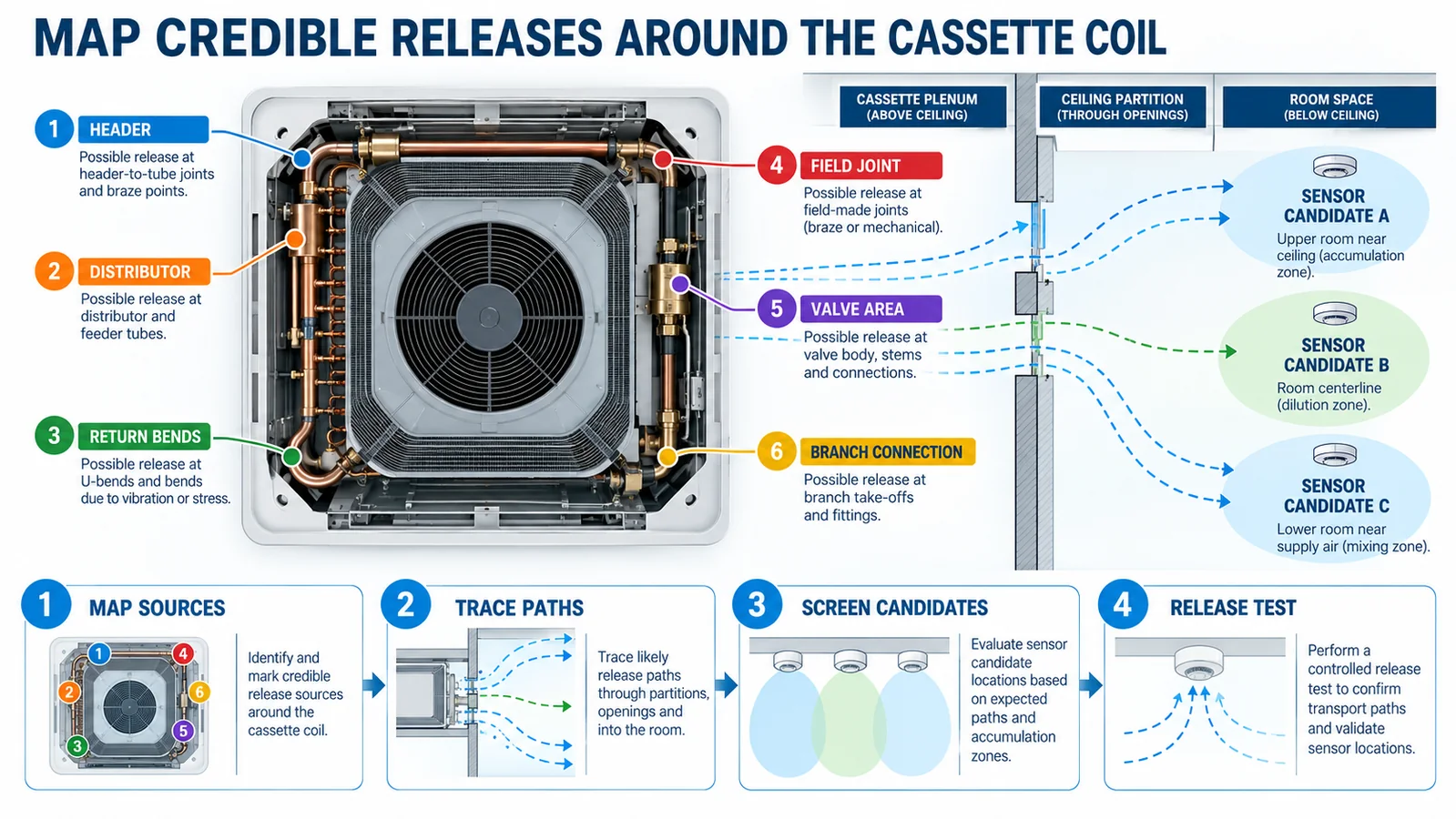
Mark headers, distributors, return bends, brazed or mechanical joints, valves, branch connections, and field piping interfaces on the production model. For each source, record the initial release direction, nearby impingement surfaces, refrigerant inventory that can reach it, and the equipment states in which it remains pressurized. A directional jet can strike sheet metal or insulation before mixing with cabinet air.
Do not reduce the analysis to “R32 is heavier than air.” Local concentration depends on release momentum, temperature, entrainment, forced airflow, cabinet geometry, and time. Gravity is important, especially after mixing and during fan-off conditions, but it is only one influence. Use engineering analysis to identify candidate transport paths, then confirm those paths with controlled releases in production-intent equipment.
The map should include sources that are easy to miss: a valve body above the pan, a distributor behind the coil frame, a field joint outside the nominal cabinet, or a return bend shielded by insulation. Link every source to at least one test case. If several sources are grouped as equivalent, retain the technical reason that the selected case is no less challenging.
Four-way airflow can move gas away from a low point
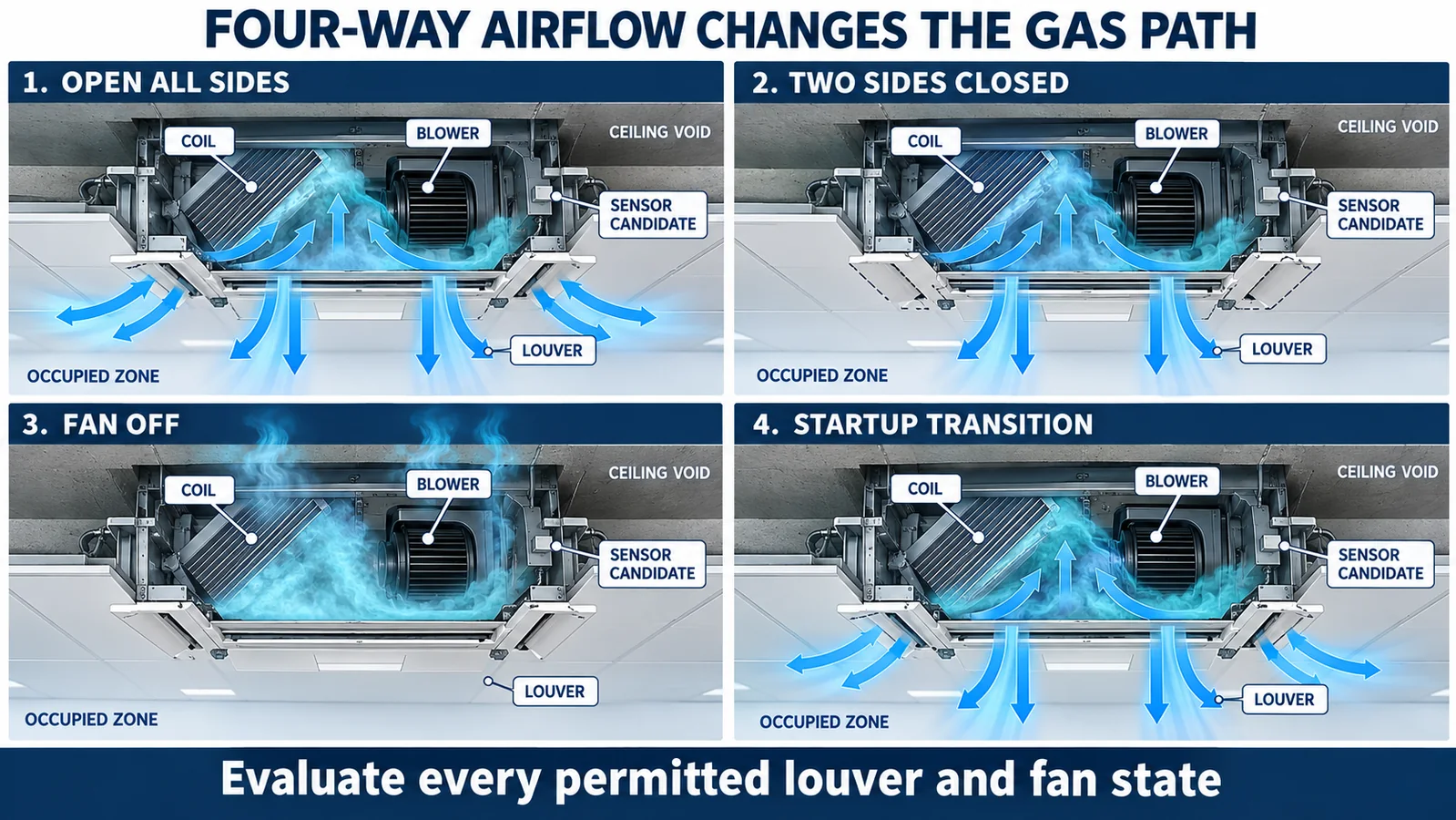
When the central fan runs, air is typically drawn through the return grille and coil and discharged along the cassette perimeter. Depending on the construction, a release can be entrained before it settles into a geometric low region. A candidate sensor mounted low but outside the main mixed-air path may respond slowly under high airflow, while a point near the fan inlet may respond well in operation but poorly after shutdown.
Characterize the actual airflow rather than the command alone. Filter loading, coil wetness, fan speed, static resistance from branch ducts, and panel fit can change velocity and recirculation. Record the commanded speed and a verified indication of fan operation in qualification tests. A stalled fan is not represented by a normal “fan on” command.
Use smoke visualization or nonhazardous flow studies only as supporting tools; they do not replace controlled refrigerant-release evidence. Flow visualization can identify recirculation and bypass, but refrigerant mixtures may behave differently because of temperature, concentration, and release conditions. The safety case should connect the qualitative airflow picture to measured reference concentration and installed-sensor response.
Louver configuration creates distinct test states
Many cassette panels allow one or more discharge sides to be closed for room layout, wall proximity, or branch-duct use. Louvers can also swing, stop at a fixed angle, or close during standby. These configurations alter both the occupied-room jet and internal pressure distribution. A sensor position qualified with all four sides open may not cover a permitted two-way or three-way configuration.
List each field-selectable louver arrangement and determine whether the controller can identify it. If the configuration is set mechanically or during installation, the instructions and commissioning record must preserve it. Test representative extremes rather than only the factory default. Include transitions such as startup, louver movement, shutdown, and power loss when they can change the gas path.
If one sensor location cannot meet the applicable requirement across all allowed louver states, the engineering choices include restricting the allowed configuration, relocating the sensor, using an additional sensing point, or changing the mitigation architecture. The choice must be reflected consistently in drawings, firmware, installation instructions, and certification evidence.
Fan-off and standby pockets deserve special attention
Standby may last much longer than an active cooling cycle. With the fan stopped, gas transport can be governed by leakage gaps, natural convection, gravity, temperature gradients, and the geometry of the pan and decoration panel. Pockets can form behind the coil frame, above the pan lip, around the pump housing, or in the ceiling recess.
Test fan-off releases at credible sources without assuming the next thermostat call will provide timely mixing. Consider whether the equipment remains powered, whether the detector remains supervised, and whether a power interruption changes the protective response. If the control concept requires the fan to start after detection, validate the full sequence from release through detection, command, verified fan operation, and subsequent dilution.
A candidate that performs well only after the fan starts may not satisfy a requirement that detection occur before mitigation. Conversely, a protected low point that is effective in standby may be bypassed during high airflow. The design has to meet both conditions or use a controlled multi-point architecture.
Heating and defrost change temperature and water conditions
In a heat-pump system, the indoor coil changes role between cooling and heating. Coil temperature, fan logic, louver position, and refrigerant distribution can therefore differ substantially. Defrost can stop or change the indoor fan and may be followed by transient airflow. Residual condensate from an earlier cooling cycle can remain in the pan even when the coil is warm.
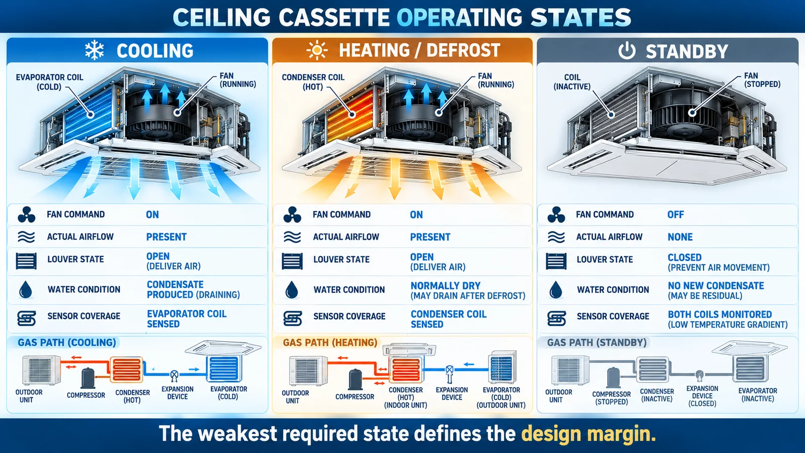
Build a state table that includes cooling speeds, heating, defrost-related indoor states, thermostat-off standby, startup, shutdown, and applicable fault modes. For every state, identify which circuit sections are pressurized, whether the fan actually runs, how the louvers are positioned, and whether water is present. Use the equipment’s real sequence rather than generic heat-pump assumptions.
The weakest required state should drive the placement margin. Do not average a fast cooling response with a slow standby result. Each approved state must meet its own pass criteria and be traceable to the controller and firmware revision used in the test.
The drain pan is both a geometric barrier and a water source
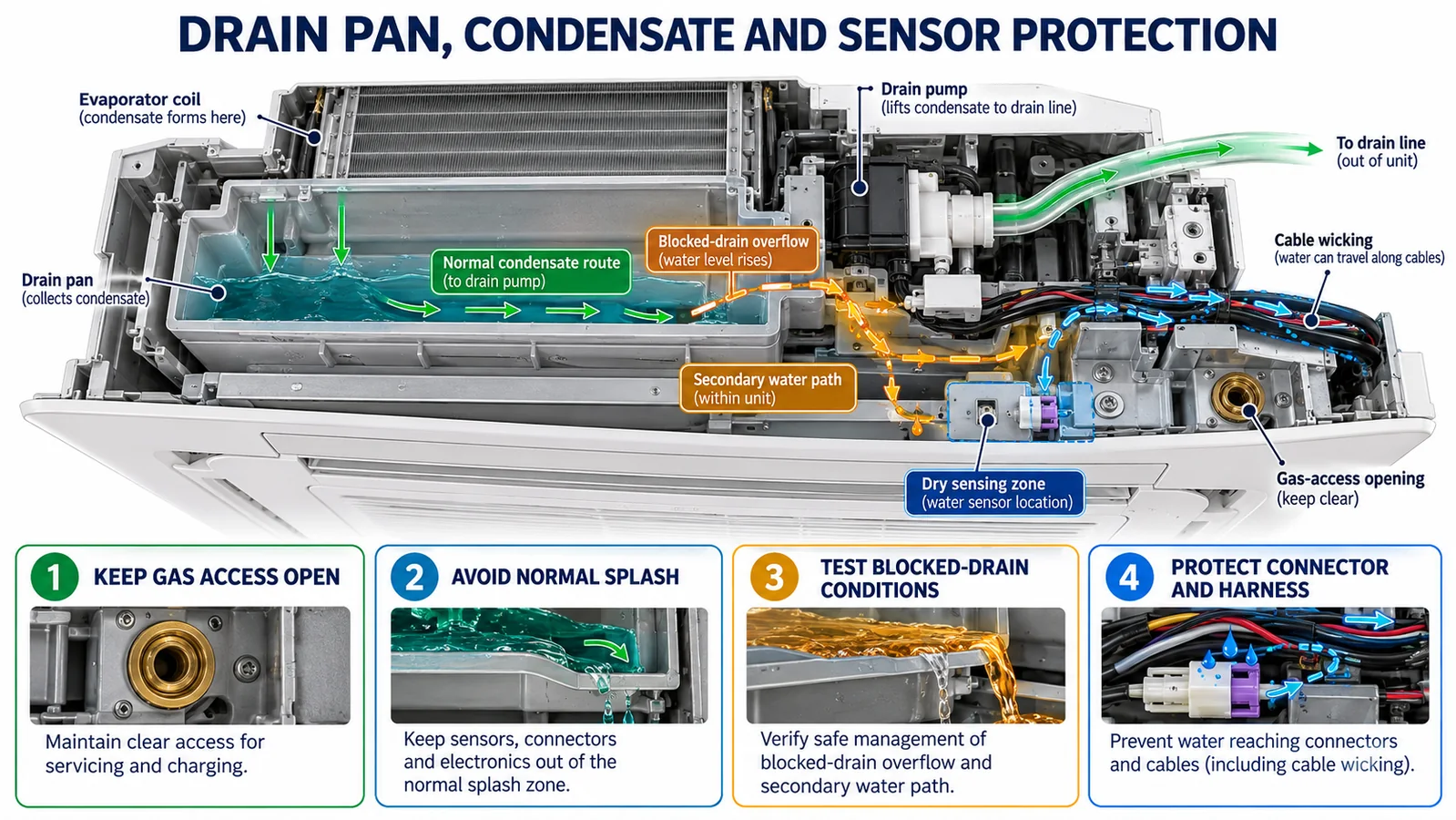
The cassette drain pan can redirect gas, form a low-volume channel, or separate the coil compartment from the room. At the same time, it collects condensate and may experience splash, pump cycling, biofilm, cleaning solution, or overflow. Mounting a detector near the pan can improve access to a plausible accumulation zone but create water and contamination risks.
Map normal condensate from the coil to the pan, pump reservoir, discharge hose, and building drain. Then map abnormal paths caused by blocked drainage, pump failure, unit tilt, damaged insulation, a disconnected hose, or a full secondary pan. Include cable wicking: water can travel along a harness into a connector even when the sensor body is outside the visible wet area.
Protecting the electronics must not seal the gas path. A cover, shield, membrane, or downward-facing inlet can change transport and response. Test the final production housing, inlet orientation, bracket, harness, and nearby clearance. A bare sensor result cannot qualify a sensor that will be installed behind a protective feature.
Drain-pump faults belong in the placement validation
The pump and float switch are not only reliability components; their state can change the detector environment. A blocked outlet or failed pump can raise the water level and expose the sensor or harness. A float-switch response may stop cooling while leaving the fan, detector, or controller in a different state. The fault logic may also produce a service alarm unrelated to refrigerant detection.
Define normal, high-water, pump-fault, and power-loss conditions in the validation matrix. Use safe water testing to reproduce credible overflow paths without compromising electrical safety. After exposure, inspect the detector, connector, seals, and harness and confirm that diagnostics remain valid. If the sensor is expected to recover after a temporary wet condition, that behavior needs controlled evidence; otherwise the instructions should require replacement or service.
Keep water faults distinguishable from gas alarms and detector faults. A technician should not interpret every cassette shutdown as a refrigerant event. Clear fault codes, event history, and service instructions reduce unnecessary replacement while preserving the safety response.
Protect the inlet without hiding it behind insulation
Ceiling cassettes often use molded insulation, foam strips, acoustic material, and field-applied seals. Production tolerance or service reassembly can move these materials close to a detector inlet. Dust from the ceiling void and debris from installation can also restrict small openings.
Specify the sensor location by controlled features: bracket part, fastener, inlet direction, surrounding keep-clear envelope, connector orientation, and harness clips. The keep-clear region should be inspectable at production and service. Avoid requirements that depend on a technician measuring from a vague edge or interpreting “near the coil.”
Review worst-case tolerance stacks. A prototype with carefully placed insulation may not represent production limits. Include alternate insulation suppliers, panel revisions, and approved service parts in the design-change assessment. End-of-line inspection can use a visual check, fixture, camera, or other suitable method, but it must verify the functional inlet remains open.
Coordinate detector wiring with cassette service access
Cassette maintenance commonly occurs from below after removal of the return grille, decoration panel, electrical-box cover, or drain components. The sensor should be accessible enough for inspection and replacement without encouraging an uncontrolled relocation. A harness routed across a filter, louver motor, pump, or sharp sheet-metal edge can be damaged during routine work.
Define connector retention, strain relief, bend radius, abrasion protection, and separation from wet surfaces. If the detector communicates digitally, preserve address or identity through replacement. If it provides an analog or discrete output, define how open circuit, short circuit, out-of-range signal, and loss of power are detected by the controller.
Service instructions should show the exact qualified position and inlet orientation. Use keyed features or a dedicated bracket where practical. After replacement, require an approved functional check of the channel, alarm path, controller mapping, and intended mitigation without instructing the technician to release refrigerant.
Keep the RDS sequence equipment-specific
An integral refrigerant detection system includes more than the sensing element. It includes the installed location, wiring, control logic, power, actuators, feedback, fault handling, and mitigation sequence. Depending on the evaluated cassette design, mitigation might involve fan operation, louver commands, compressor control, shutoff devices, external ventilation, or annunciation. No single sequence is correct for every product.
Write a state-based cause-and-effect table. Separate a confirmed gas alarm from a detector fault, communication loss, fan failure, drain fault, and controller restart. Define which actions latch, what evidence permits reset, and how the system behaves if an actuator does not reach the commanded state. If a building controller receives status, make sure the local protective function does not depend on a cloud or supervisory service unless that dependency is explicitly evaluated.
The controller should confirm actual behavior where it matters. A fan command is not the same as verified airflow, and a louver command is not proof that the blade moved. The level of feedback required is a system safety decision and should be documented.
Build an end-to-end response-time budget
The installed system response begins when refrigerant leaves the circuit, not when a bench sensor sees a prepared gas sample. The total includes transport from the source to the inlet, diffusion or flow through the protective structure, sensor measurement, signal filtering, communication, controller decisions, actuator movement, and any verified feedback.
Allocate the timing budget without hiding transport uncertainty inside the sensor specification. Measure both the reference concentration near the installed inlet and the detector output so engineers can distinguish a placement problem from an electronic response problem. Repeat the slowest sources and states across environmental and production corners.
Do not copy a timing value from a component page into the equipment safety case. Product data can help screen candidates, but the certified equipment response is established by the applicable test method and production-intent assembly. Retain time histories rather than only a pass/fail summary; they are essential for later design changes.
Commission the installed cassette, not just the controller
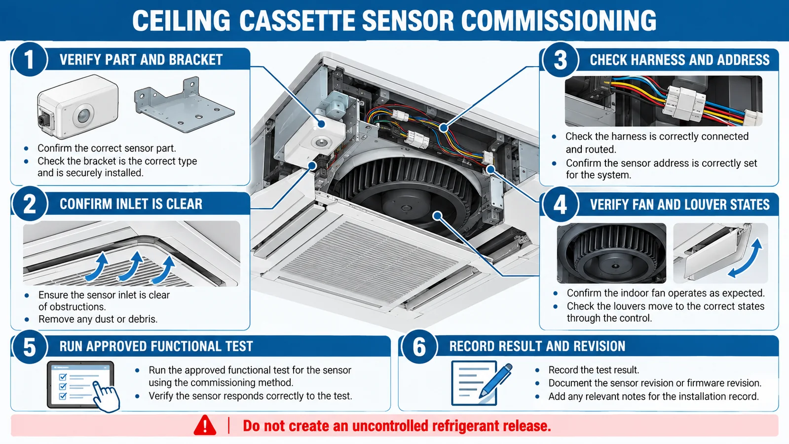
Commissioning should verify the sensor part, bracket, inlet clearance, connector, harness, address, controller configuration, fan and louver states, fault reporting, and approved functional test. The record should link the physical indoor unit to its controller object and room designation. This is especially important in multi-zone systems with several similar cassettes.
The functional test must follow the equipment manufacturer’s approved method. Field personnel should not create an uncontrolled refrigerant release. If an electrical or simulated method is used, understand what it proves: it may verify wiring and logic without proving gas transport or sensing-element performance. Keep equipment qualification evidence separate from installation commissioning.
After the test, confirm the system returns to the permitted state, event logs are correct, and no temporary test mode remains active. Record the unit model, sensor revision, controller software, configuration, date, and result.
Use a source-by-state validation matrix
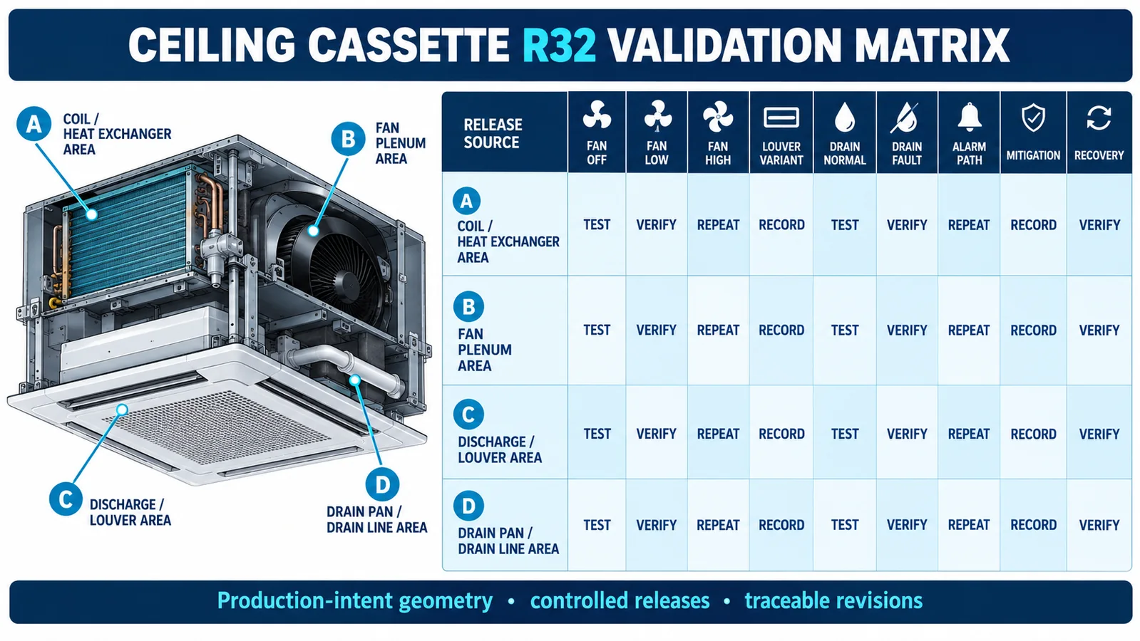
Cross every credible release source with the required fan speeds, louver variants, operating modes, drain conditions, ambient limits, and fault states. Add columns for reference concentration, detector signal, alarm transition, controller command, actuator feedback, and recovery. The matrix should make gaps visible rather than compressing all evidence into one “representative” test.
Use production-intent coils, panels, filters, insulation, pans, pumps, wiring, covers, and firmware. Instrumentation should not open a new gas path or obstruct the natural one. Photograph the setup, record revisions, and retain raw traces. Repeat marginal or variable cases until the engineering team understands the cause and can establish a robust margin.
The illustration below is a planning example, not product performance data. Your released matrix must contain the applicable acceptance criteria and results approved for the equipment program.
Control model variants and field options
A cassette family may share a decoration panel across several capacities while changing coil diameter, cabinet height, fan, piping, or pump. Those changes can affect gas transport even when the sensor bracket looks unchanged. Maintain a compatibility table linking every indoor-unit model, panel, sensor, bracket, harness, controller version, and validated configuration.
Optional branch ducts, fresh-air kits, high-lift pumps, occupancy sensors, and louver-blocking kits need an impact review. The same applies to site conditions such as a sealed ceiling recess versus an open return plenum if those conditions are within the approved installation scope. Unsupported combinations should be blocked in selection tools and instructions.
When a change is proposed, identify whether it affects refrigerant inventory, release direction, internal volume, airflow, water path, detector environment, communication, or mitigation. Focused retesting is appropriate only when the technical basis is documented.
Add manufacturing controls for the qualified gas path
The placement study only remains valid if production equipment preserves the tested path. Convert critical geometry into drawing notes and inspection points. The bill of material should control the detector, bracket, cover, membrane or screen, connector, harness clips and any foam or insulation close to the inlet. Work instructions should show orientation and cable routing with photographs or unambiguous views.
Define tolerances for inlet-to-wall clearance, bracket position and drain-pan relationship where they affect response. End-of-line inspection should detect a reversed bracket, blocked opening, missing seal, trapped cable or incorrect fascia. If the detector communicates digitally, read and record its model, firmware or configuration identifier where supported; electrical continuity alone cannot prove the intended part is installed.
Audit production-intent samples from different shifts and tooling cavities. A manually prepared prototype can have cleaner openings and more generous clearance than a high-volume assembly. Retain measured examples of limiting configurations and connect them to the release-path evidence.
Plan maintenance around contamination and water history
The ceiling location hides the cassette from routine observation. Service instructions should identify the detector inlet, prohibit painting or covering it, and explain which cleaning products and spray directions are allowed. Technicians should inspect for dust mats, insects, insulation fibers, condensate residue and evidence of overflow without inserting tools into the sensing opening.
A previous drain blockage can matter even after the pan is dry. Water may leave residue on a membrane, connector or protective grille. Define the inspection, drying, functional check and replacement criteria after overflow or pressure washing. If a detector is replaced, require the approved part and restored orientation, then verify alarm/fault communication and the equipment-specific control sequence before closing the ceiling.
Product integration example: compact UART sensing
Winsen’s MH-Z1542B-R32 is listed in the verified WooCommerce export as an NDIR sensor for R32 with UART output. The official product data presents it as a compact embedded sensor. That makes it a possible candidate for an OEM evaluation where board space and a serial interface are relevant, but it does not establish an approved cassette location or equipment-level response.

Confirm refrigerant calibration, supply and interface limits, warm-up behavior, diagnostics, response definition, dimensions, environmental range, lifetime evidence, and certification scope using the current controlled documentation. The cassette manufacturer remains responsible for the final RDS architecture, mounting, wiring, control sequence, production checks, and qualification.
Related guides include R32 sensor integration in wall-mounted mini-splits, R32 sensor location and airflow geometry, R32 leak-alarm control sequencing, i orientation-dependent sensor placement.
What to send for a cassette design review
Provide the refrigerant and maximum charge, cassette models and capacity range, coil and piping drawings, decoration-panel and louver options, ceiling-boundary assumptions, fan curves and states, drain pan and pump design, credible release analysis, proposed sensor zones, controller interface, alarm and fault concept, environment, annual volume, and certification market.
Winsen can review the candidate sensor interface and help structure a source-by-state validation matrix. The review should begin before the bracket, harness, controller I/O, and qualification unit are frozen, because placement and control decisions interact.
Contact Winsen for an R32 ceiling-cassette sensing review.
Referències
- Solucions UL: inspecció de sistemes de detecció de refrigerants en equips de climatització
- Solucions UL: Requisits actualitzats per als sistemes de detecció de refrigerants
- Solucions UL: Resposta del sensor en sistemes HVAC
- Iniciativa de recerca de refrigerants inflamables AHRI
- AHRTI 9009: Detecció de fuites de refrigerants A2L en equips HVACR
- Daikin Round Flow Cassette product and documentation page
- Winsen MH-Z1542B-R32 product page
