
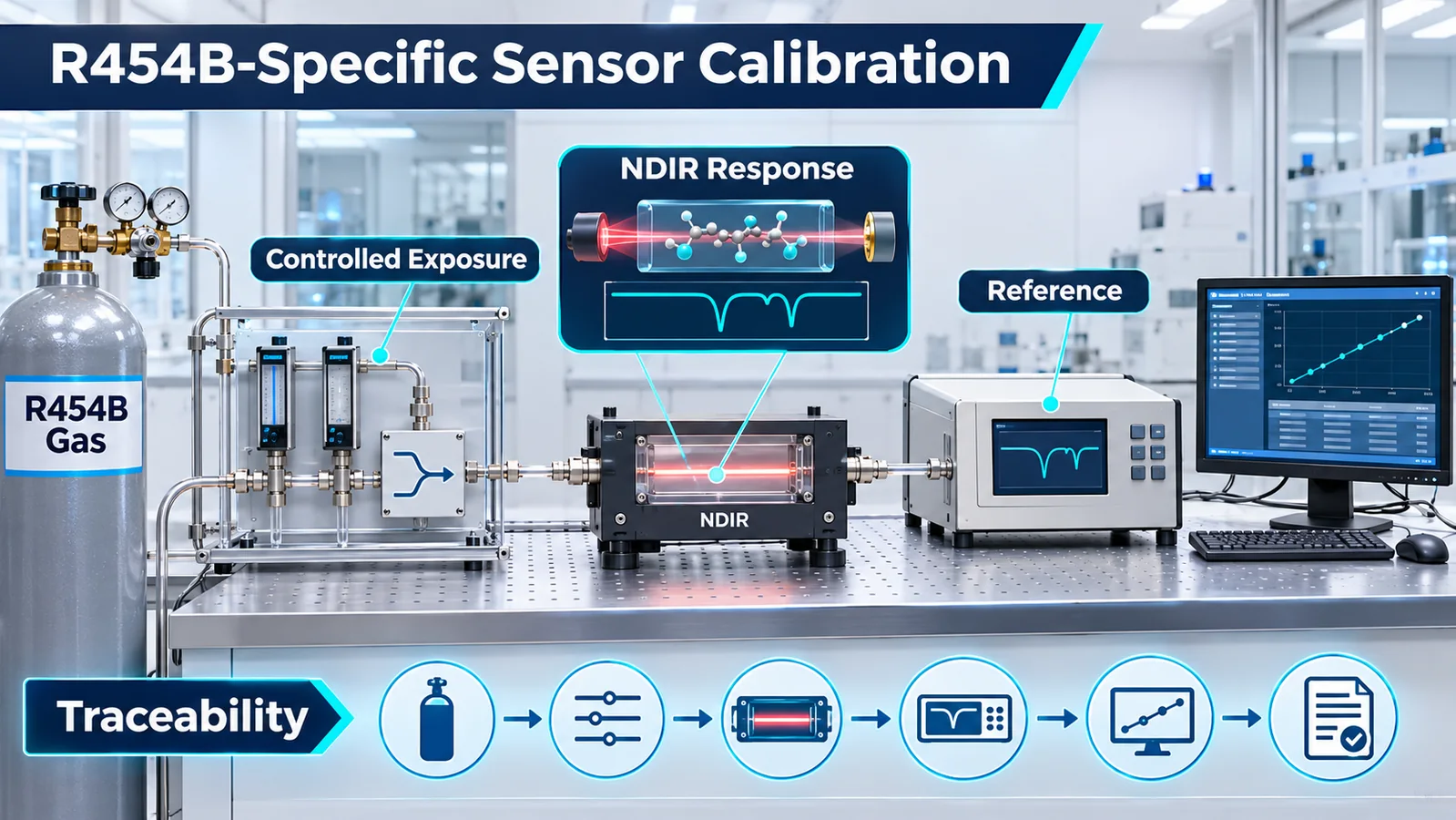
A refrigerant sensor does not measure “leak” as an abstract property. It measures a physical response—such as infrared absorption—and converts that response into a concentration or alarm state using a model for a defined gas, optical path, environment and hardware. If the calibration model does not match the refrigerant, the reported number can look precise while being wrong for the safety decision.
That is the core of R454B sensor calibration specificity. R454B is a named refrigerant blend with its own infrared response and flammability basis. An R32-calibrated or generic hydrocarbon curve cannot be assumed equivalent. Gas identity, concentration unit, calibration traceability, environmental compensation and controller threshold ownership must remain linked throughout design and production.
This article explains the engineering chain without prescribing a universal threshold or claiming that a sensor module establishes equipment compliance. Use controlled refrigerant data, current detector documentation, applicable equipment requirements and project certification evidence.
1. Calibration Is a Measurement Model
Calibration establishes a relationship between detector signal and a defined measurand under controlled conditions. For an NDIR refrigerant detector, the raw signals may include a measurement channel, reference channel, source monitoring, temperature and other diagnostics. Firmware uses coefficients or a model to estimate concentration or determine an alarm state.
The output is meaningful only when the assumptions are known: target refrigerant, concentration preparation, carrier gas, pressure, temperature, humidity, flow or diffusion setup, optical path, hardware revision, software revision and reference instrument. “Calibrated” without these details is incomplete.
The HVAC controller receives the result, not the laboratory context. Therefore the interface must carry or imply the correct gas and unit. Configuration control links the installed sensor model to the controller interpretation. A wrong model can produce a plausible zero at clean air and plausible movement during a leak while still applying the wrong scale.
2. Understand Gas-Specific NDIR Response
NDIR sensing uses infrared absorption in wavelength regions associated with the target gas. The optical filter, source, detector, path length and algorithms determine sensitivity and selectivity. Different refrigerants can absorb differently within the instrument band. Blends add complexity because components and composition define the response.
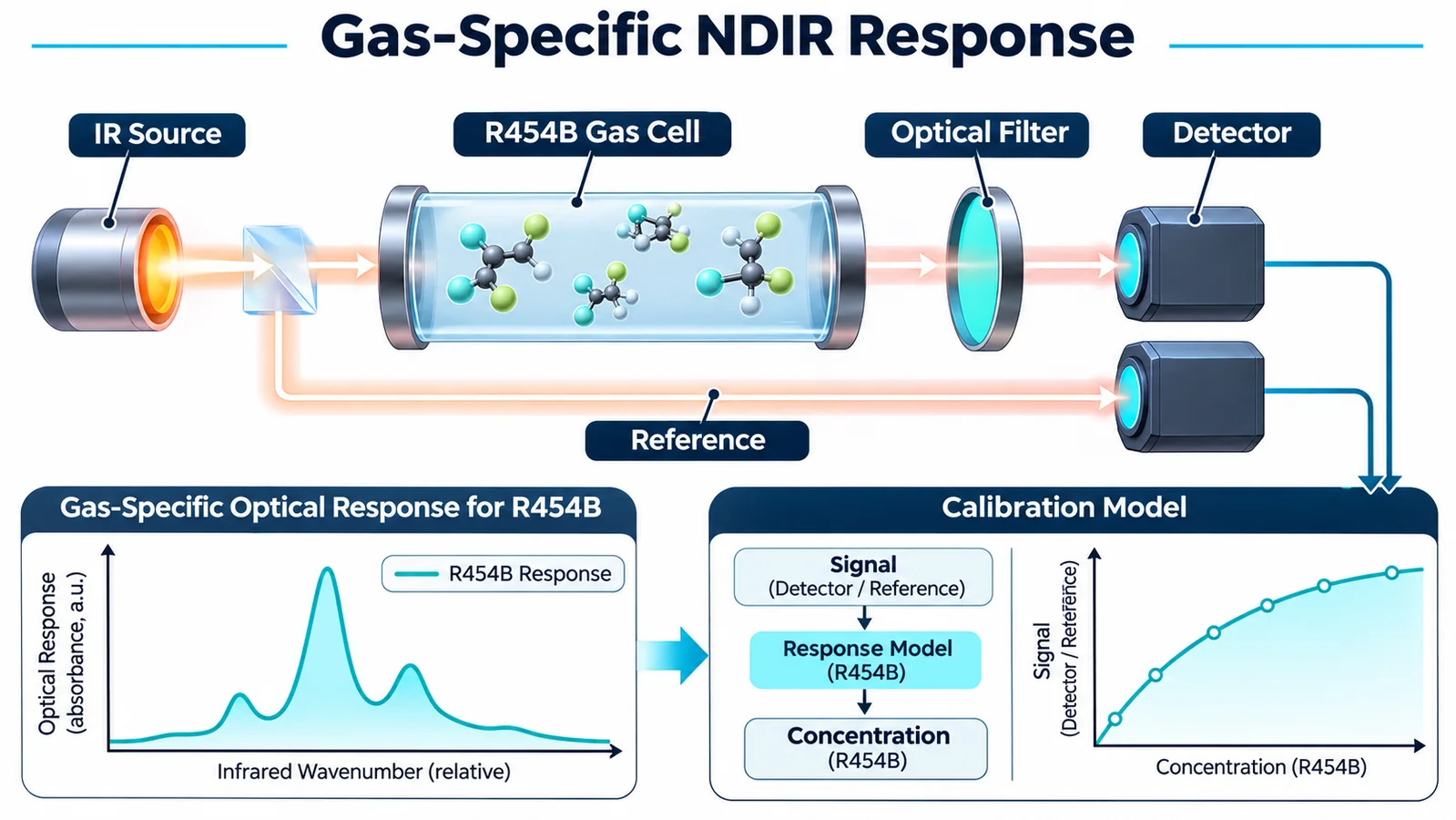
The response is not guaranteed to be linear across the required range. Temperature, pressure, optical contamination and source aging can change signal. The calibration model may use multiple coefficients, lookup tables or compensation surfaces rather than a single slope.
Because two refrigerants both contain fluorinated molecules does not mean one curve can be renamed. The supplier should provide evidence for the exact R454B variant and output. Cross-response data can help interpret other gases, but it is not a substitute for target-gas calibration.
The complete module—including any membrane, enclosure or diffusion path—must be characterized. Changing a cover or filter can alter transport time even if the optical calibration remains unchanged.
3. Define the Refrigerant Identity Precisely
The equipment bill of material and software configuration should name R454B explicitly. Avoid ambiguous labels such as “A2L mode” or “refrigerant sensor” when multiple gases use similar hardware. The detector part number, calibration identifier and controller parameter set must point to the same refrigerant.
For blends, use controlled refrigerant specifications and gas-preparation procedures. Calibration gas composition, cylinder traceability and handling can affect the realized concentration. Supplier and OEM quality teams should agree on acceptable gas sources and evidence.
If a sensor family supports R32, R454B and other variants, treat each ordered calibration as a distinct controlled part unless the supplier’s controlled design explicitly provides validated multi-gas identification. Shared housing and product photography do not establish interchangeability.
Electronic identity can reinforce part control. The controller may read model, gas code, firmware or calibration version and compare it to the expected equipment configuration. If such identification is unavailable, manufacturing and service processes must provide equivalent protection.
4. Keep Concentration Units Explicit
Common representations include volume fraction, ppm by volume and percent of lower flammability limit. They are not interchangeable labels. A numerical value without unit and gas identity is unsafe data.
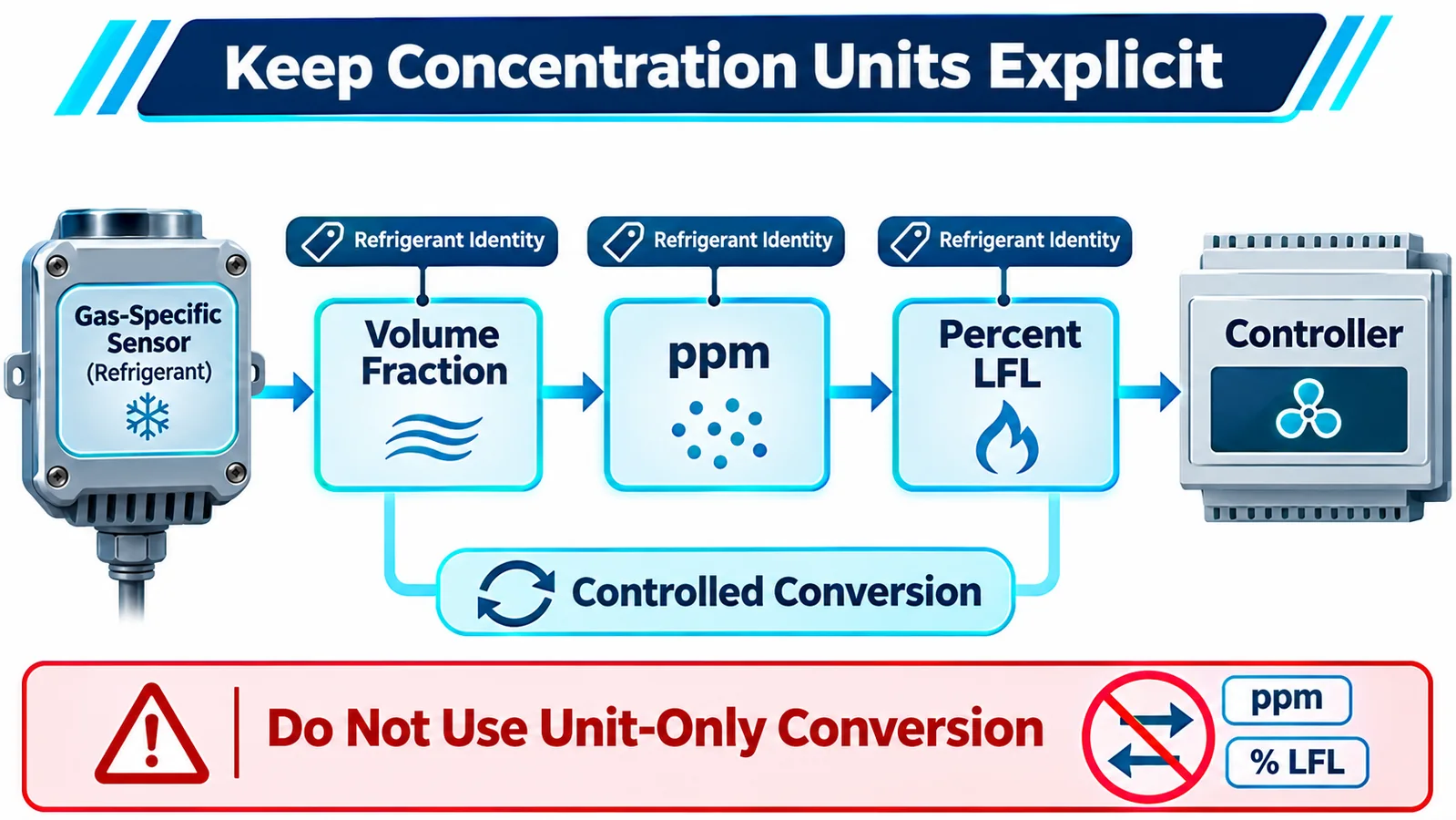
If the sensor reports volume concentration and the controller uses percent LFL, the conversion requires a controlled R454B flammability basis and consistent reference conditions. The property source, value revision and calculation location must be documented. Do not scatter rounded constants across sensor firmware, controller code and test scripts.
If the sensor reports percent LFL directly, confirm which gas calibration and property basis it uses. The controller should not apply a second conversion. Interface documentation must distinguish concentration, alarm state, raw signal and diagnostic values.
Test unit handling with known engineering vectors. Include boundary, invalid and mismatched configuration cases. A software display can show the right unit while the underlying scale is wrong; verify the complete data path.
5. Separate Calibration From Alarm Threshold Ownership
Calibration converts sensor response to a quantity. The equipment safety design decides how that quantity or a detector alarm is used. A factory preset inside the detector, a controller threshold and an applicable equipment requirement are related but not automatically identical.
Assign ownership. Define where the released threshold resides, who can change it, how tolerance is considered and how the value is verified. Avoid duplicate adjustable values that can diverge. If the detector owns a preset alarm, the controller should interpret its semantics exactly. If the controller owns the decision, it needs a validated concentration and unit.
No generic article value should replace the applicable equipment requirement and certification design. UL Solutions discusses factory preset/calibration and system-response requirements in the context of refrigerant detection systems; the current controlled standard and certification decision govern a specific product.
Configuration changes should require authorization, versioning and regression tests. Field service must not be able to select another gas or threshold casually.
6. Characterize Cross-Gas and Interferent Response
Target-gas calibration does not eliminate response to other substances. HVAC environments can include other refrigerants, coil cleaners, adhesives, sealants, lubricants, aerosols, alcohols, combustion products and cleaning vapors. Humidity and condensation can affect transport or optics.
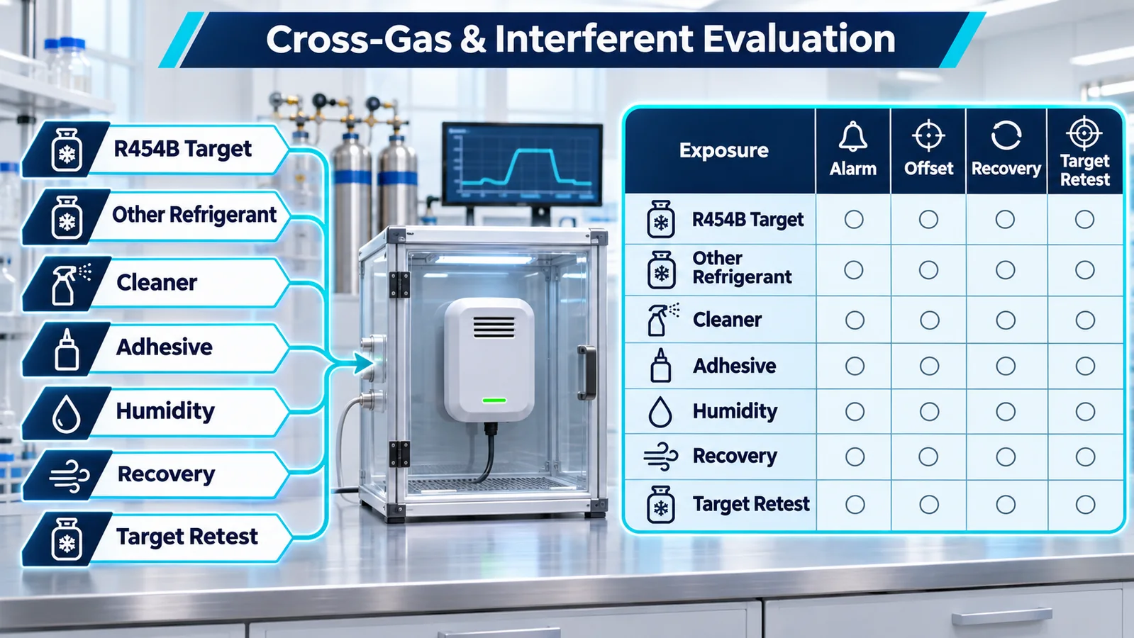
Create an interferent list from the actual equipment materials, manufacturing process, installation and service chemicals. Prioritize credible concentrations and exposure durations. Evaluate alarm, offset, recovery time, diagnostic behavior and permanent change.
Cross-response can be positive, negative or masking. A substance may create an apparent signal, suppress target response or contaminate the diffusion path. Testing should include target gas after interferent exposure to confirm recovery.
Supplier data are useful for screening, but the OEM should cover its approved chemical list and application conditions. If instructions prohibit certain cleaners, make the restriction clear and provide alternatives. A detector should not be located in a routine spray path.
7. Model Temperature, Humidity and Pressure Effects
Sensor output and gas transport vary with environment. Temperature affects infrared source/detector behavior, gas density and electronics. Humidity can affect optical surfaces, membranes and condensation. Pressure changes the number of absorbing molecules in the optical path and may affect concentration interpretation.
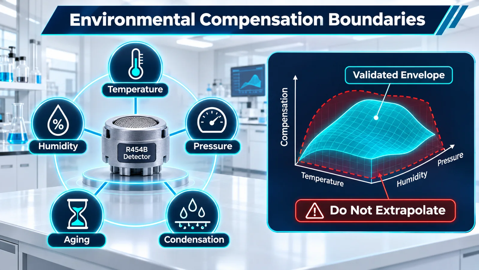
Compensation is an empirical model with a valid domain. Define the characterized temperature, humidity and pressure range and the transitions inside it. Do not extrapolate silently beyond supplier evidence. Condensation is often a separate condition, not merely high relative humidity.
Validate the installed module at relevant equipment conditions, including rapid transitions, cold start, warm enclosure and wet-to-dry recovery. The bracket and protective cover can create local conditions different from ambient sensors.
Include environmental sensors or internal diagnostics in plausibility analysis where the architecture supports it. If compensation inputs fail, the module should report a defined fault or degraded state rather than an unqualified concentration.
8. Include Manufacturing Tolerance and Drift
Calibration must cover unit-to-unit variation in optics, electronics, path geometry and assembly. Production adjustment can reduce variation, but acceptance limits and verification points need to reflect the full range.
Long-term drift can come from source aging, optical contamination, component drift and material changes. The applicable product requirements and supplier evidence define how life performance is demonstrated. The OEM should understand how drift affects the system threshold and response budget.
Use guard bands based on characterized error sources rather than optimistic nominal accuracy. Combine calibration uncertainty, gas preparation, environmental effects, repeatability, drift and controller quantization/filtering. The correct method depends on the safety architecture and controlled requirements.
Do not hide uncertainty by rounding the display. The engineering analysis needs the underlying tolerance even if the operator sees a simple alarm state.
9. Build a Traceable Production Calibration Process
A production calibration station should control gas identity, concentration generation, flow/exposure fixture, temperature/pressure as needed, reference instrument, stabilization, software and acceptance criteria. Prevent line mix-up between refrigerant variants.
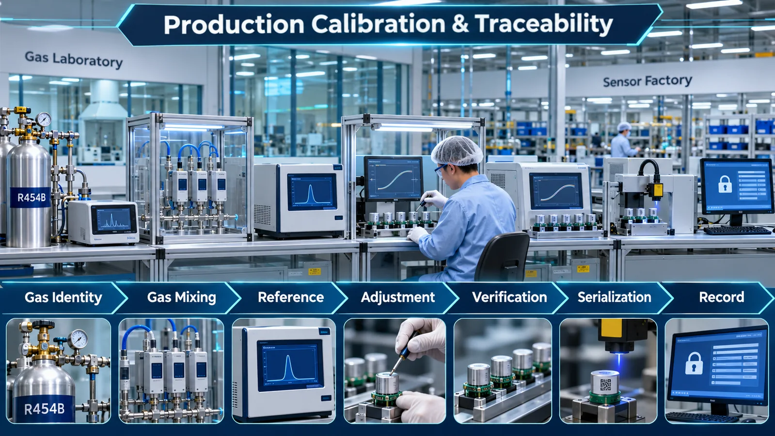
Trace each unit or lot to calibration gas, reference equipment status, station software, coefficients, results and operator/fixture identity. Use automated range and identity checks to reduce manual entry errors. Protect calibration data from uncontrolled editing.
Separate adjustment from verification. After coefficients are written, verify at independent points or conditions defined by the control plan. Include zero/clean-air handling and reject behavior. A unit should not pass because the same erroneous reference generated and verified its curve.
Monitor station trends. Drift in gas delivery, reference analyzer or fixture sealing can shift many units while each appears internally consistent. Use control samples, audits and cross-station comparisons.
Define a reaction plan before trends move outside control. Quarantine affected production, preserve station data, confirm gas delivery and reference performance, and assess the last known-good point. Reverification should use an independent method where practical. The investigation must determine whether the issue changed calibration, response timing, identity data or only the station record, because each outcome affects product disposition differently.
10. Control Zeroing and Baseline Algorithms
Zero-point management can improve stability, but it can also learn away a persistent leak if assumptions are wrong. Understand whether the module performs automatic baseline correction, zero-point self-calibration or commanded zeroing. Define when it is permitted and what clean-air condition is required.
A field zero should not be performed merely because the current reading is inconvenient. If zeroing is part of service, instructions must ensure a refrigerant-free environment as required by the controlled design and applicable requirements. Log the event and configuration.
Test slow leaks and long-duration low concentrations against baseline algorithms. Verify that target response is not suppressed. Test power cycles and memory corruption. If coefficients or baseline state are stored in nonvolatile memory, include integrity checks and safe behavior for invalid data.
The controller should know when output is invalid during zeroing or warm-up. A temporary zeroing state must not look like valid clean air.
11. Verify the Digital or Analog Data Chain
For digital interfaces, confirm scaling, byte order, signedness, units, gas code, update rate, checksum, invalid codes, fault bits and timeout. Test corrupted frames, frozen counters, duplicate addresses and partial updates. The controller should reject invalid data deterministically.
For analog interfaces, define output range, source impedance, controller input tolerance, open/short behavior, grounding and conversion. Verify the full stack from sensor output through ADC and software scaling. Voltage near a normal value does not prove the correct gas variant is connected.
If both analog and UART outputs exist, do not assume they share timing, filtering or alarm semantics. Select the released interface and verify it. Avoid using one path for control and another for diagnostics unless disagreement behavior is defined.
Maintain engineering test vectors for concentration, alarm, fault and invalid states. These protect against firmware changes that accidentally alter scale or unit.
12. Integrate the MH-441D-454B Conservatively
Winsen lists the MH-441D-454B as an NDIR R454B sensor. Current local product evidence indicates analog-voltage and UART-related outputs but also notes that detailed output descriptions require controlled-document confirmation. Exact range, response, supply, protocol, environmental limits, mechanics, diagnostics and life evidence must be verified for the ordered revision.

Request the full model code, R454B calibration definition, mechanical drawing, inlet orientation, electrical specifications, output transfer function, protocol, warm-up and validity behavior, fault modes, compensation limits, calibration/traceability evidence and change-notification process.
Do not publish or design from web-page specifications where conflicts exist. The controlled datasheet, protocol and project quality agreement govern. A product family statement cannot substitute for variant-specific evidence.
The sensor supplier can provide component characterization; the HVAC OEM must validate installed gas transport, controller interpretation, thresholds, environmental exposure, production controls and equipment response.
13. Manage Calibration and Firmware Changes Together
Hardware, optical filters, source drive, enclosure, membrane, coefficients, compensation and firmware can all affect response. Any change needs impact assessment. A firmware-only revision may alter filtering or timing even if the calibration curve remains nominally the same.
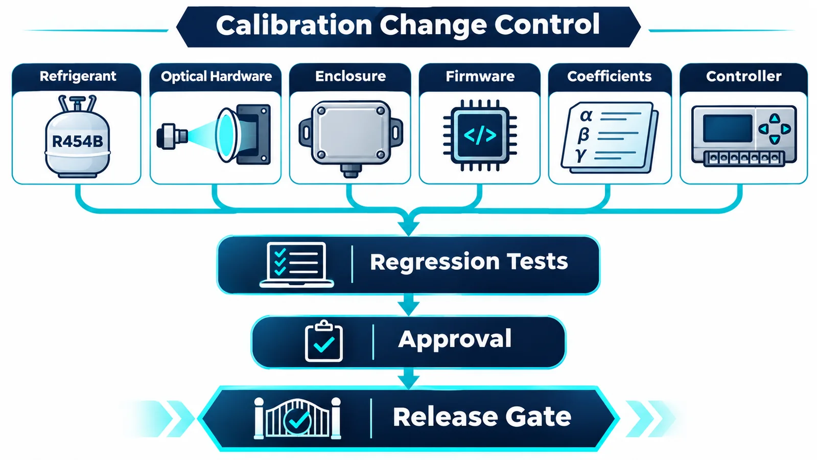
Maintain a compatibility matrix linking sensor hardware, gas, calibration version, sensor firmware, protocol and HVAC controller software. Define allowed combinations and rejection behavior. Manufacturing and service tools should enforce the matrix.
Regression tests should include target-gas points, environmental corners, interferents, startup, alarm/fault semantics, communication and system mitigation. Repeat installed response tests when timing or diffusion paths change.
Supplier changes need advance notification with enough evidence for OEM review. Do not accept “form, fit and function unchanged” when the function includes gas response and safety timing.
14. Create a Calibration Validation Matrix
The matrix should vary:
| Domain | Representative factors |
|---|---|
| Target gas | controlled R454B sources and concentration points |
| Environment | temperature, humidity, pressure and transition states |
| Hardware | production lots, optical/electronic tolerance and relevant aging |
| Interferents | approved cleaners, materials and credible refrigerants/vapors |
| Data path | analog/digital scaling, unit, invalid codes, timeout and faults |
| Algorithms | warm-up, filtering, baseline/zero, compensation and alarm state |
| System | installed bracket, airflow, controller threshold/action and feedback |
| Change | firmware, coefficients, supplier and mechanical revisions |
Define uncertainty and acceptance before testing. Use traceable reference instruments and controlled gas preparation. Record raw signals where possible, not only pass/fail output.
Repeat limiting conditions and include target response after interferent/environmental conditioning. A detector that recovers to zero but loses sensitivity has not demonstrated acceptable recovery.
15. Engineering Release Checklist
Confirm that:
- The installed part and controller configuration name R454B explicitly.
- Calibration gas, method, reference and environmental conditions are controlled.
- The NDIR response model is validated for the exact hardware and R454B variant.
- Output quantity and unit are unambiguous end to end.
- Any percent-LFL conversion has one controlled source and owner.
- Calibration and equipment alarm-threshold ownership are distinct and documented.
- Credible cross-gases, cleaners and vapors are characterized.
- Compensation boundaries and condensation behavior are defined.
- Manufacturing tolerance, uncertainty and drift are included.
- Production adjustment and independent verification are traceable.
- Baseline/zero algorithms cannot hide a credible leak.
- Digital or analog faults and stale data are detected.
- Hardware, calibration, firmware and controller compatibility is controlled.
- Product claims rely on current controlled evidence.
If the team cannot state the gas, unit and calibration revision behind a number, the controller should not use that number as valid safety data.
16. Audit the Complete Evidence Chain
Before release, take one finished production unit and trace backward. Read its detector identity and configuration. Find its calibration record, gas source, station software and reference status. Confirm the controller firmware interprets the same gas and unit. Link the equipment threshold configuration to its approved requirement and test evidence.
Then trace forward. Expose the installed detector using the controlled system method, capture the reported value or alarm, follow the controller state, observe physical mitigation and confirm the service record. This end-to-end audit finds gaps that separate component and software reviews miss.
Repeat the audit for a replacement part and a rejected mismatch. Verify that wrong-gas or incompatible revisions cannot silently enter normal operation. Include any field configuration tool and access controls.
Maintain the evidence chain after changes. A new cylinder supplier, calibration station, firmware build or controller revision should update the linked record and trigger defined regression. Traceability is not an archive; it is how the current product proves that every conversion still means what the safety design expects.
17. Manage Calibration Gas and Laboratory Uncertainty
Calibration quality depends on the gas delivered to the sensor, not only the cylinder label. Define how R454B test concentrations are prepared, verified and introduced. Consider cylinder certification, blend handling, regulators, tubing adsorption, leaks, flow control, chamber mixing, purge, residual gas and reference-analyzer response. Use materials compatible with the refrigerant and concentration range.
Create an uncertainty budget for the calibration or verification result. Contributions can include certified gas uncertainty, dilution accuracy, reference analyzer, chamber uniformity, environmental measurement, timing, repeatability and unit resolution. The acceptance rule should account for uncertainty so a borderline unit is not accepted simply because the test system reads favorably.
Verify spatial uniformity and transport in fixtures. A station can deliver the correct nominal mixture while the sensor inlet receives a delayed or diluted concentration because of fixture geometry. Periodically compare stations with control units and independent references. Trend zero, span, response and recovery, not only pass rate.
Purge and contamination control are especially important on lines that handle multiple refrigerants. Use dedicated or validated changeover paths, gas identity interlocks and blank checks. A small residual from another gas can bias calibration while remaining invisible in the production record.
Document metrological traceability and calibration intervals for reference equipment. Define actions when a reference is found out of tolerance, including assessment of previously accepted units. This closes a common gap between laboratory procedure and production quality.
18. Validate Threshold Robustness Without Inventing a Universal Value
The equipment team should evaluate the released threshold against the entire response chain without treating one nominal number as sufficient. Combine sensor error and drift, environmental effects, gas transport, sampling, filtering, communication latency, threshold logic and actuator time. The goal is to demonstrate the required system response under limiting conditions.
Use concentration ramps, steps and transient profiles representative of the validation method. Test values below, near and above the released decision region to characterize false transitions, persistence and recovery. Include noise, stale data and fault conditions. Keep the exact acceptance criteria in controlled project documents rather than copying a generic online value.
Check hysteresis and latching. A real leak may fluctuate near the decision point as fans start or gas disperses. The controller should not chatter between states or reset before released recovery conditions are satisfied. Filtering should reject noise without delaying a credible rise beyond the response budget.
When a threshold changes, treat it as a safety-relevant configuration change. Link the new value to requirement, analysis, calibration version, firmware and regression evidence. Confirm manufacturing and service tools cannot leave mixed configurations in the field.
19. Use Field Data Without Recalibrating Away Problems
Field trends can reveal drift, contamination and installation issues, but remote zeroing or coefficient changes should not be used to silence unexplained alarms. Preserve raw and diagnostic history, inspect gas exposure and installation, and follow the controlled service process.
Returned-unit analysis should compare detector response with its production calibration, controller logs, environmental history and physical condition. Examine inlet blockage, cleaner residue, condensation, connector faults and wrong variant/configuration. A bench pass after cleaning does not prove the field system was correct.
If fleet data justify an algorithm or calibration update, define the affected population, compatibility, deployment controls and post-update verification. Safety-related changes need the same evidence discipline as new production. Keep previous coefficients and audit records so the change can be reconstructed.
Secinājums
R454B sensor calibration is gas-specific measurement engineering. Optical response, units, environment, drift, production traceability and controller interpretation must form one controlled chain. A precise-looking output is useful only when that chain is correct for R454B and preserved through manufacturing, firmware changes and service.
For a technical review, provide the refrigerant, expected quantity/unit, detector model/revision, interface, environmental range, threshold ownership, controller architecture, approved chemicals, annual volume and target certification market.
Atsauces
- UL Solutions — Updated Requirements for Refrigerant Detection Systems
- UL Solutions — Sensor Response in HVAC Systems
- AHRI — Flammable Refrigerants Research Initiative
- AHRTI 9009 — Leak Detection of A2L Refrigerants in HVACR Equipment
- Copeland — A2L Refrigeration Overview
- Winsen — MH-441D-454B NDIR Refrigerant Sensor
