
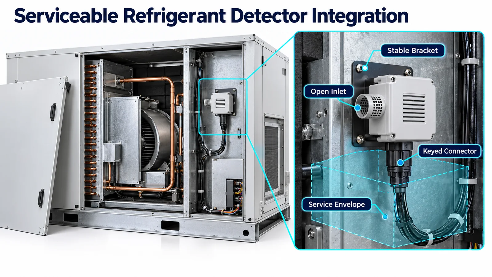
A refrigerant detector can pass every bench test and still become unreliable after routine HVAC service. A technician removes a panel, the panel pulls the harness, the connector is reinstalled one position off, insulation moves across the inlet, coil cleaner enters the sensing path, or a replacement module is mounted in the wrong orientation. None of these failures begins in the sensing algorithm. They begin in the mechanical and service design.
좋은 refrigerant sensor service access preserves four things every time the unit is opened: the detector’s qualified location, representative gas exposure, correct electrical/configuration interface and traceable post-service verification. The goal is not merely to make the sensor reachable. It is to make correct service repeatable while making incorrect assembly difficult and visible.
This guide is intended for HVAC mechanical, electrical, controls and serviceability engineers. It describes a design method, not a universal installation rule. The equipment manufacturer must align the released construction and instructions with the applicable equipment requirements, target refrigerant, controlled detector documents and certification evidence.
1. Define What Service Must Accomplish
Start with service tasks, not with a panel seam. List the operations that may affect the detector during the expected equipment life: filter replacement, coil cleaning, drain maintenance, blower removal, heat-kit service, control-board replacement, refrigerant-circuit repair, insulation replacement, sensor inspection and sensor replacement. Add factory rework and field retrofit if either is allowed.
For each task, record whether the detector must remain installed, be disconnected, be temporarily protected, be removed, or be functionally verified afterward. Identify the tools, hand clearance, line of sight, body posture and access direction. Include protective equipment and the real connector latch motion. A CAD clearance cylinder that ignores a gloved hand or screwdriver angle does not represent the service process.
The service concept should define the safe final state. For example, after coil cleaning the inlet must be uncovered, dry and unobstructed; the harness must be in its retained route; the correct gas variant must be connected; diagnostics must report valid operation; and any required system-level function check must pass. These become design requirements for panels, brackets, connectors, software and instructions.
2. Reserve a Real Service Envelope
The detector needs an envelope for access and an envelope for sensing. They overlap but are not identical. The access envelope includes the hand, tool, connector withdrawal, fastener path and module extraction path. The sensing envelope includes open space around the gas inlet, a representative air path and clearance from surfaces that could block or redirect gas.
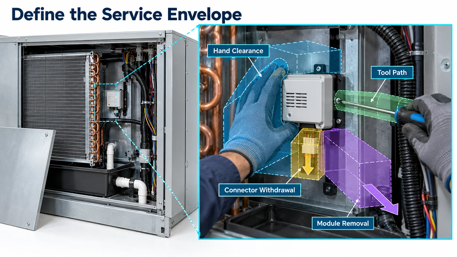
Model both envelopes in the master assembly. Check them with adjacent production parts at tolerance extremes: insulation, tubing, cable bundles, drain hoses, control boxes, filter frames and optional accessories. Consider panel deflection and how a technician is likely to rest a removed panel. A nominal gap can disappear when foam expands, a harness relaxes or a sheet-metal flange shifts.
Avoid making another safety-critical part the “tool” used to reach the detector. If a technician must bend a tube, remove a drain, disturb a seal or unplug unrelated controls, the service procedure creates secondary risk. Prefer a direct, observable path. If access requires sequential removal, make the sequence clear and ensure intermediate states do not place load on the sensor or harness.
Document the envelope with datums and minimum clearances in the mechanical drawing. A note saying “keep area clear” is hard to inspect. A defined keep-out zone, connector pull direction and inlet clearance can be checked in design reviews and production audits.
3. Prevent the Panel From Moving the Sensor
A common integration error is mounting the detector on a removable cover without treating the cover motion as part of the harness design. The first time the panel opens, the cable becomes a hinge or a tensile member. The connector can partially unlatch without appearing disconnected, or the panel can be reinstalled while pinching the cable against a sharp flange.
Where practical, mount the detector to a stable chassis datum and let the service panel expose it. If the detector must be panel-mounted, design a controlled service position, adequate slack, strain relief on both moving and fixed sides, abrasion protection and a connector arrangement that cannot carry the panel weight. Define whether the connector is disconnected before the panel can be moved beyond a limited angle.
Use retention that survives repeated cycles. Clips should not relax after heat exposure, and adhesive mounts should not be the sole positioning control unless their life and environment are validated. Screws need appropriate retention and torque controls. Captive fasteners reduce lost hardware near electrical or blower components.
Test the real opening motion through the intended service cycle count. Observe harness bending, connector load, inlet clearance and final routing. Repeat after thermal and vibration conditioning because a route that is stable on a new unit may migrate after service life exposure.
4. Protect the Gas Inlet From Service Contamination
Service access introduces contaminants that normal operation may not. Coil cleaner, disinfectant, adhesive vapors, sealants, lubricants, dust, insulation fibers and water can contact the detector. Some may temporarily change output; others may block the diffusion path or damage materials. The risk depends on sensing technology, product construction, exposure concentration and recovery conditions.
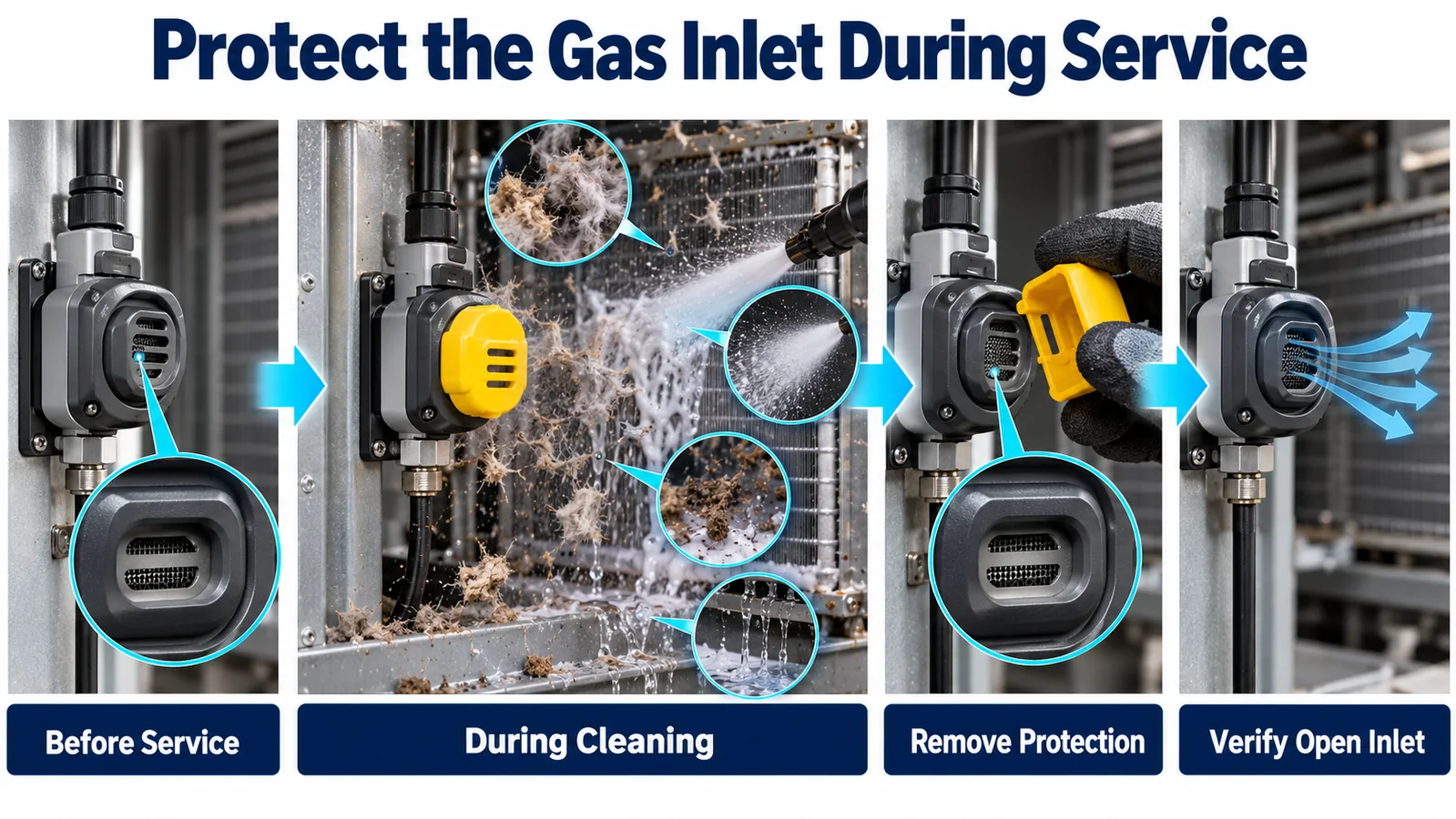
Locate the detector outside direct spray and drip trajectories where possible. Provide a shield for droplets or falling debris only if the shield maintains representative gas exchange. Avoid fine screens or filters added without response testing; they can clog, absorb refrigerant, hold cleaner or delay diffusion. Any protective membrane or enclosure becomes part of the qualified detector assembly and needs change control.
If the detector must be covered during cleaning, use a dedicated, highly visible temporary cover tied to the service procedure. The cover should be difficult to leave in place unnoticed. A brightly colored tether, interlock, service flag or closeout checklist may be appropriate. Do not rely on memory hidden behind a panel.
Define approved chemicals and application methods. Obtain compatibility and interferent guidance from the detector supplier, then evaluate the actual HVAC cleaning products and exposure patterns allowed by the manual. A recovery test should confirm that the detector returns to valid operation; a simple absence of immediate alarm is not sufficient evidence.
5. Engineer Harness Routing and Strain Relief
The electrical path is part of the detector function. Map it from power and controller to the module, including connectors, splices, clips, grommets, protective sleeving and any service loop. Keep it away from hot surfaces, sharp edges, condensate paths, high-voltage conductors and moving blower parts. Where crossings are unavoidable, define separation and protection.
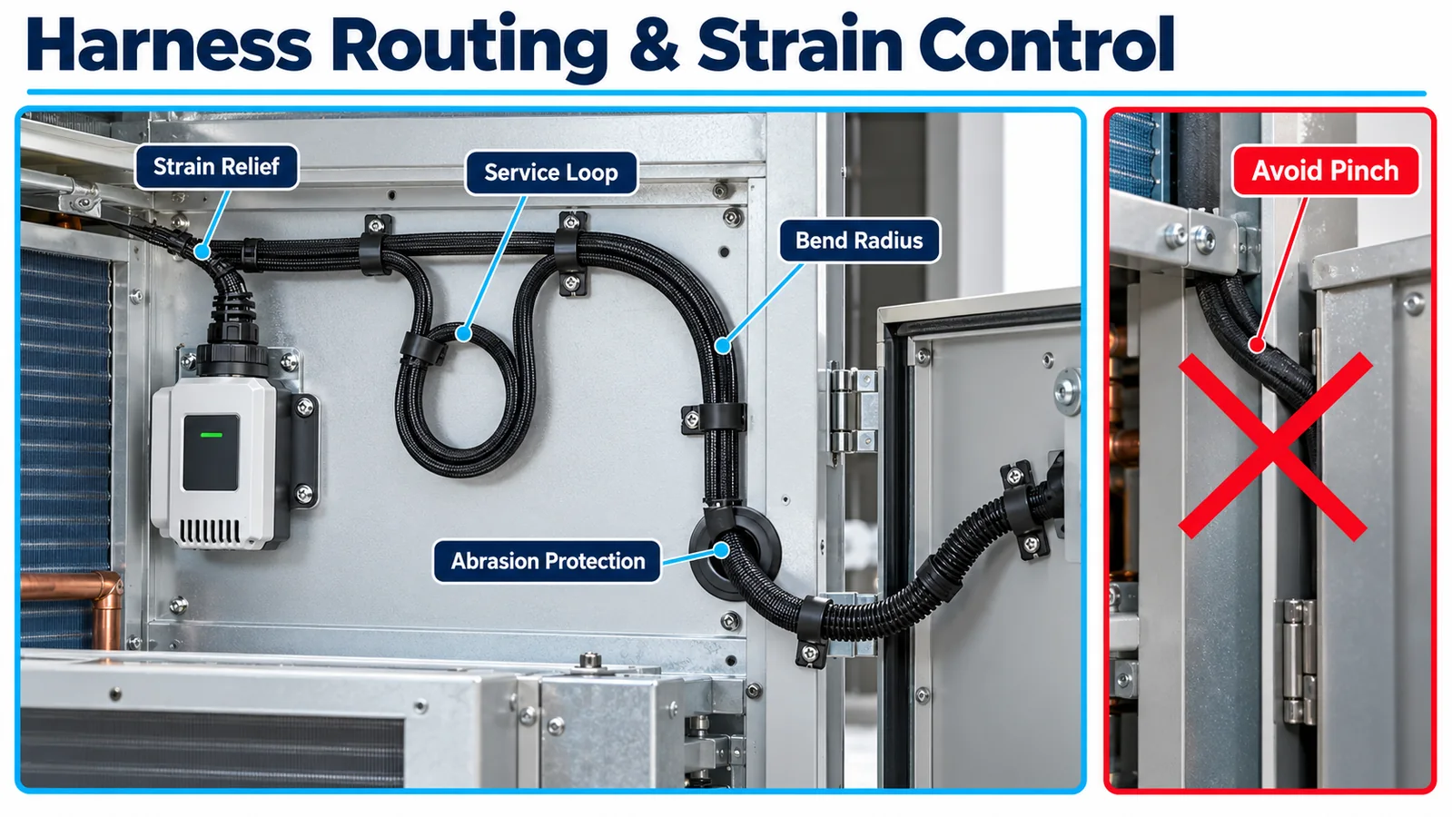
Place strain relief so normal service loads are transferred to structure, not to terminals or the sensor housing. Maintain the specified bend radius at the connector. A tight bend can push the connector sideways and change the detector orientation. Excess slack can enter the airflow path, rub a wheel or lie across the gas inlet.
Harness length tolerances need a home. Provide a repeatable service loop or retained path instead of allowing the assembler to store extra wire anywhere. Verify routing at minimum and maximum cable length, with all panel and accessory variants. Use clips that can be reopened without damage if the service procedure requires it, and define replacement if a single-use tie is cut.
Electrical diagnostics should detect credible harness faults. Depending on the interface, these may include open circuit, short to supply or ground, out-of-range analog values, invalid frames, checksum errors, missing updates and frozen data. The exact diagnostics belong to the controlled protocol and controller design, not to assumptions based on wire count.
6. Use Keying and Poka-Yoke for Replacement
Refrigerant detectors may share housings while differing in gas calibration, output, supply or firmware. Physical interchangeability is convenient for manufacturing but dangerous if the wrong variant can produce plausible data. The replacement design should make gas and interface mismatch difficult to create and easy to detect.
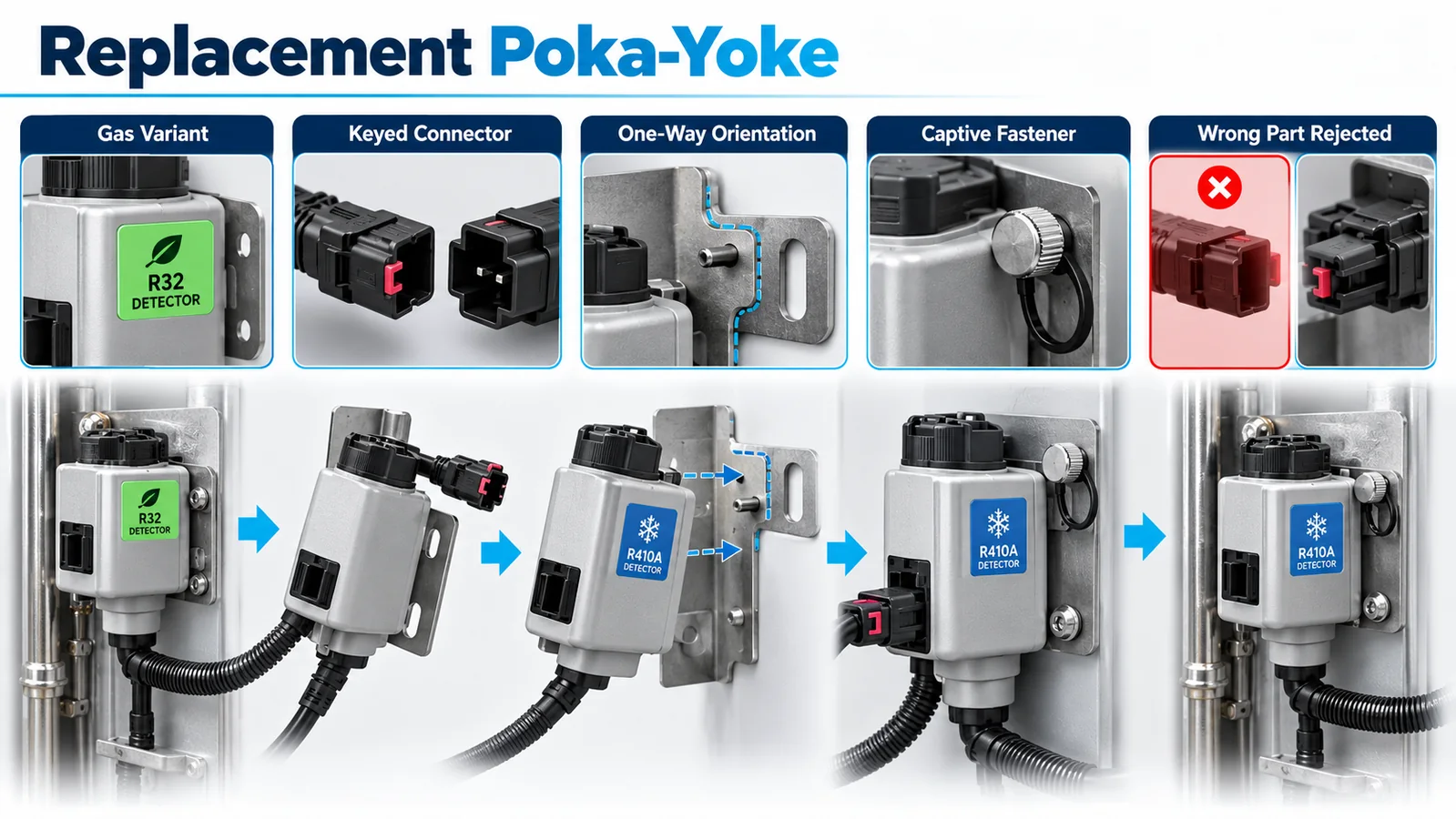
Use a combination of part-number control, keyed connectors, asymmetric mounting, color or shape coding, electronic identification and controller configuration checks. Labels alone can be hidden or copied incorrectly. Electronic identification alone may not protect a system that accepts a generic response. Layer controls in proportion to the consequence.
Orientation also needs poka-yoke if it affects gas access, drainage or connector stress. An asymmetric bracket, locating pin or one-way clip is stronger than an arrow that becomes invisible after installation. Fasteners should be unique enough to prevent use of a longer screw that could damage a board or block an inlet.
Define the replacement unit as a controlled service part. The service bill of material should specify refrigerant, module revision, approved firmware or calibration, bracket, hardware and any seal or membrane. If replacement changes system configuration, the controller must be updated through a protected workflow and the final record must capture that change.
7. Keep Configuration Traceable to the Hardware
A detector’s meaning depends on its refrigerant calibration, output definition and software interpretation. The installed part, controller firmware and configuration parameters must agree. A service event that replaces any one of them can break that alignment without producing an obvious mechanical error.
Create a configuration identity that can be inspected. It may include detector model and revision, gas, serial or lot number, controller software version, protocol map, calibration version and threshold configuration. The exact data set depends on the architecture, but it should be enough to show that the released combination is present.
Where the detector communicates digitally, the controller can compare reported identity or configuration with the expected equipment record. Where such data are unavailable, use service tooling or controlled part-number processes. Do not infer gas identity from a normal-looking concentration value. A wrong-gas sensor may still report plausible numbers while applying the wrong response model.
Change control should cover detector supplier revisions, alternate components, connector changes, bracket changes, protective membranes, firmware, controller sampling, filtering and thresholds. Seemingly small changes can affect gas transport, timing or fault coverage. The service organization needs the same change notice that production receives.
8. Separate Self-Test From System Verification
An internal self-test can be valuable. It may check electronics, optical signals, memory, supply, watchdog behavior or other internal functions. It does not automatically prove that refrigerant can reach the inlet, that the correct gas calibration is installed, that the bracket is in the qualified position, or that the blower and other mitigation devices respond.
Service documentation should state exactly what a diagnostic proves. A post-service sequence can be layered:
- visual inspection of location, inlet, bracket, harness and connector;
- power-up and warm-up observation;
- confirmation of valid identity, data and diagnostic state;
- interface fault checks appropriate to the service performed;
- functional alarm or test input, if supported and defined;
- verification of controller commands, actuator feedback and annunciation;
- gas-response or system-release test where required by the released plan.
This prevents a “self-test passed” message from closing a service order when the inlet remains capped. It also avoids unnecessary gas exposure when a repair did not affect the sensing or mitigation path and the controlled service plan permits a narrower check.
9. Define the Post-Service Workflow
The closeout workflow should be written while the equipment is being designed, not after the first field complaint. It must fit the tools and skills available to the intended technician. Include safe power conditions, access steps, connector inspection, protection removal, harness restoration, diagnostics, functional checks, panel closure and final records.
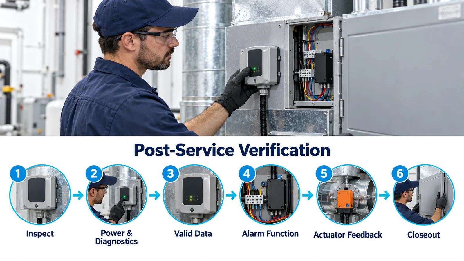
Sequence matters. A diagnostic performed with the panel open may not represent the final gas path. A cable that is correct before panel closure can be pinched during closure. Therefore include a final inspection or diagnostic after the unit is restored to its operating construction. If the detector cannot be seen afterward, use features that provide confidence without reopening the unit.
Define acceptance and failure actions. What happens if the sensor never reaches valid state, reports a fault, has a mismatched identity, or produces an alarm during cleaner recovery? Does the unit remain locked out? Which service information is displayed? Who is authorized to reset a latched state? Ambiguity encourages bypasses.
For recurring maintenance, keep the procedure concise and visual. For sensor replacement, provide deeper instructions and traceability steps. Both should point to the controlled equipment documentation rather than generic online advice.
10. Validate Service-Induced Failure Modes
A serviceability design review should include realistic misuse and error cases. Use a failure-mode analysis to rank them, then reproduce important cases on hardware. Examples include:
- panel opened without first disconnecting the specified connector;
- connector partially seated, latch broken or terminals backed out;
- harness routed on the wrong side of a drain or sharp edge;
- extra cable stored across the inlet;
- temporary cleaning cover left installed;
- sensor rotated or bracket installed in an alternate hole;
- wrong refrigerant or interface variant fitted;
- cleaner applied more heavily than instructed;
- wet connector energized after cleaning;
- insulation or a replacement filter blocking the sensing zone;
- controller board replaced with default parameters;
- sensor fault reset without correcting the cause.
Test whether the design prevents the error, detects it, or leaves it latent. Prevention is usually strongest; detection provides a second layer. A warning in text is the weakest control when the physical assembly invites the mistake.
Run repeated service cycles after environmental conditioning. Check torque retention, clip wear, connector insertion force, harness abrasion, bracket position and inlet contamination. Use gas or tracer tests to confirm that repeated panel work did not alter response. Record the final construction and acceptance criteria.
11. Design the Controller for Service States
The HVAC controller should have explicit behavior for sensor disconnection, warm-up, replacement and post-service checks. If a connector is removed while the unit is powered, the controller should transition to a defined fault rather than preserve the last valid reading. If the sensor reports a new identity, the controller should verify compatibility before returning to normal operation.
Service modes need access control and timeout. A diagnostic override that suppresses mitigation can become a permanent unsafe state if it is easy to leave active. Display the mode clearly, limit its duration where appropriate and log its use. Do not allow a service command to rewrite gas calibration or safety thresholds without authorization and traceability.
Recovery logic should distinguish a repaired fault from a transient return of communication. Require sufficient valid data and any defined checks before normal operation resumes. If an alarm or fault is latched, document whether reset is automatic, local manual or service-tool controlled. The decision belongs to the released equipment safety concept.
The controller log should help diagnose field issues without encouraging technicians to bypass the detector. Useful records include state transitions, timestamps, sensor identity, diagnostic codes, communication quality, mitigation commands, actuator feedback and reset source.
12. Select and Document the Detector Variant Conservatively
Winsen lists the MH-441D family as an NDIR refrigerant sensor for several refrigerant-specific applications and indicates analog and UART-related output options in current product information. The local product export also notes that output descriptions need controlled-document confirmation. For a real design, request the exact gas variant, model code, protocol, electrical interface, supply, warm-up, diagnostics, mechanical drawing, environmental limits, material compatibility and calibration evidence.

Do not treat a family photograph as proof that variants are interchangeable. A module calibrated for one refrigerant cannot be assumed correct for another because the enclosure looks the same. Likewise, an output described on a web page may not match the ordered option or protocol revision. Freeze the exact part and document set in the equipment bill of material.
The detector supplier should also define handling, storage, cleaning restrictions, ESD precautions, replacement criteria and change notification. The HVAC manufacturer must validate the module in its installed airflow, contaminants, thermal environment, control system and service process.
13. Build Traceability Into the Service Record
Service traceability should answer: what equipment was serviced, why, which detector was present before and after, which configuration was loaded, which checks were performed, what results were obtained and who authorized return to service. This does not require excessive paperwork if the data are captured by the service tool and linked to equipment identity.
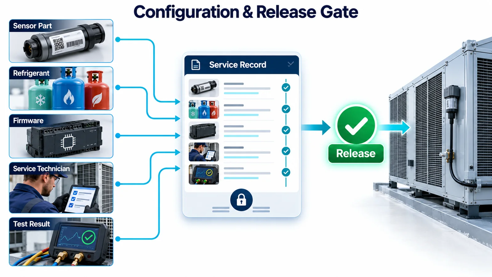
At minimum, capture the equipment model/serial, refrigerant, detector part and revision, controller software/configuration, fault or alarm history relevant to the work, replaced parts, inspection result and final verification status. If gas was used, record the controlled method and gas identity/traceability appropriate to the procedure.
Traceability supports more than audits. It reveals repeated connector damage, cleaner exposure, wrong-part substitutions and early-life failures. Trend analysis can guide a bracket change or service bulletin before a latent issue becomes widespread. Ensure the feedback loop reaches engineering and supplier quality.
14. Release Checklist for Serviceable Integration
Before releasing the equipment and service documentation, verify:
- Every permitted maintenance task has a defined relationship to the detector.
- Hand, tool, connector and module-removal envelopes are proven on production-intent hardware.
- Panel motion cannot load, pinch or misroute the harness.
- Inlet keep-out and drainage features are dimensioned and inspectable.
- Approved chemicals and protection/recovery steps are documented.
- Temporary covers or service modes cannot easily remain active unnoticed.
- Bracket, connector and part controls prevent wrong orientation or variant.
- Controller diagnostics cover open, short, invalid, stale and identity/configuration faults appropriate to the interface.
- Self-test coverage and limitations are stated.
- The post-service sequence verifies the final closed construction and required mitigation path.
- Repeated service-cycle and environmental tests preserve mechanical and sensing performance.
- Replacement parts and software are linked by configuration control.
- Service results feed warranty, quality and engineering review.
If the only control for a high-consequence error is “technician must remember,” improve the physical or diagnostic design before adding more warning text.
15. Convert Field Feedback Into Design Improvement
The first production units and service events should be treated as engineering evidence. Review connector faults, unexplained alarms, cleaning-related recovery, damaged brackets, blocked inlets, replacement-part mismatches and repeated reset attempts. A single event may be misuse; a pattern usually points to an interface that is too easy to misunderstand or disturb.
Structure returned-part analysis so that the installed context is not lost. Preserve photographs of location and routing, controller logs, configuration identity, environmental condition, service history and the exact reason for replacement. Testing a returned detector on a clean bench can show whether the module still functions, but it cannot reveal that insulation covered the inlet or a panel loaded the connector.
Feed findings into mechanical poka-yoke, diagnostics, instructions and training. If technicians routinely need to move an unrelated component, redesign the access path. If a cap is left installed, change the cap and closeout control. If wrong variants fit, strengthen physical or electronic keying. If field checks cannot distinguish a transport problem from a sensor problem, improve diagnostic coverage and the service test method.
Set ownership for periodic review rather than waiting for a serious incident. Engineering, quality, service and the detector supplier should agree on data thresholds that trigger investigation. When a design change results, update the service bill of material, drawings, software compatibility table, work instructions and regression plan together. Serviceability remains controlled only when the field configuration, documentation and engineering baseline stay synchronized.
결론
Service access is successful when the detector can be inspected or replaced without changing the system that was qualified. That requires a stable datum, a protected but open inlet, controlled harness motion, keyed parts, explicit controller states and a closeout workflow that proves more than internal electronics. The best service design makes the right assembly natural, the wrong assembly difficult and a latent error detectable.
For an OEM integration review, provide the refrigerant, equipment architecture, service tasks, panel motion, detector location, harness drawing, candidate module and output, cleaning chemicals, controller diagnostics, replacement strategy, annual volume and target certification market. Those details allow the detector and service concept to be evaluated together.
참고자료
- UL Solutions — Inspecting Refrigerant Detection Systems in HVAC Equipment
- UL Solutions — Updated Requirements for Refrigerant Detection Systems
- UL Solutions — Sensor Response in HVAC Systems
- AHRI — Flammable Refrigerants Research Initiative
- AHRTI 9009 — Leak Detection of A2L Refrigerants in HVACR Equipment
- Winsen — MH-441D NDIR Refrigerant Sensor
