
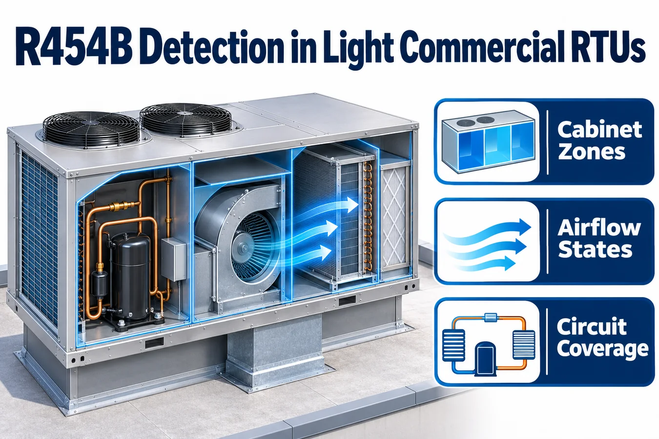
An R454B sensor rooftop unit design begins with the appliance configuration. A packaged unit may put the outdoor coil, indoor coil, return path, supply fan, economizer and refrigerant piping in a single cabinet. The leak paths and control dependencies still change when the OEM revises a bulkhead, offers a different fan or adds a second circuit. The engineering question is whether the selected sensing assembly and the equipment response work for the configurations the factory will ship and technicians will service.
Use the exact model, refrigerant designation, certification documentation and OEM instructions to define that scope. UL Solutions describes an integral refrigerant detection system (RDS) as one or more stationary sensors coupled to automatic mitigation and explains that, where required, the system is evaluated as part of the appliance certification. A module data sheet can inform selection. The unit-level evaluation defines how detection and mitigation are integrated. UL Solutions guidance on inspecting integral RDS installations
Define the model family before choosing the sensor
Start with a configuration ledger, one row per buildable combination that could alter leak transport, electronics, mounting or mitigation. Capture cabinet size, coil and drain-pan revision, refrigerant circuit arrangement, indoor fan type and controller, economizer, return and supply openings, and approved field conversions. Add model prefixes and suffixes and record where a serial range changes the bill of materials. The ledger should point to the controlled drawings behind each classification so reviewers can reproduce it after a product revision.
The same model prefix can span meaningful design differences. Carrier’s 48FE product page separates rooftop units and supporting documentation by model range, including R-454B models. In another Carrier R-454B rooftop family, the 48K specifications distinguish a single-circuit evaporator configuration from a dual-circuit intertwined coil across capacity ranges. That is an applied rooftop example of the configuration issue. The light commercial OEM should use its own bill of materials to determine where that boundary falls. Carrier WeatherMaker 48FE documentation · Carrier WeatherMaker 48K specifications
Give each proposed validation group a physical rationale. Models with the same outline may require separate groups if the coil face, drain routing or low-speed fan envelope changes. Two sizes might share evidence when cabinet features and test margins support the claimed equivalence and the responsible certification review accepts it. Document the basis for each inheritance decision and identify the test result or drawing that would invalidate it. Otherwise, a later change to a supposedly common component can silently expand the claim.
Map plausible release and collection zones
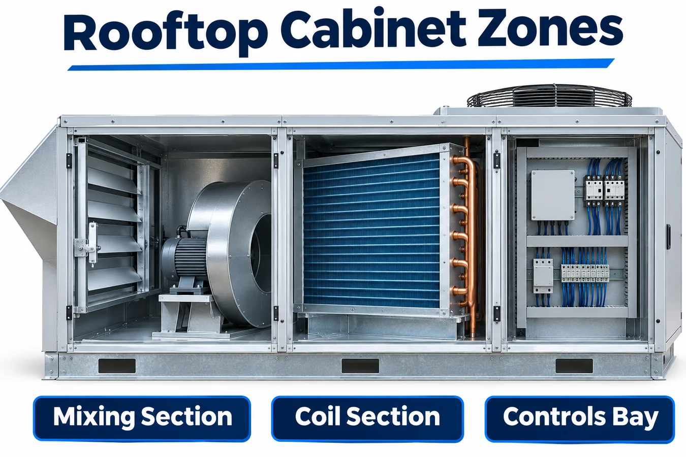
Review the cabinet by separating the source of a release, the transport path and the sensing location. A refrigerant-bearing joint near a cabinet floor could discharge into a pocket isolated by a lip. A higher joint near a return-air opening might have a short route into the air stream when the blower operates. A shared indoor coil bay could collect a release from either refrigerant circuit while routing the two releases toward different pockets with the fan idle.
Use a section drawing with the production panels installed. Mark tube penetrations, drain traps, pan edges, seal locations, wiring pass-throughs and the gap around removable components. Trace both indoor and outdoor paths where an outdoor-side release could migrate through the cabinet toward the occupied air path. Assign a source ID to each scenario and show where the test release represents it. A change to the location of a service joint or the addition of an insulation strip can then be linked back to a specific scenario.
UL Solutions describes near-coil, lower enclosure locations as typical under the evaluation criteria and points inspectors to the manufacturer instructions for actual mounting. Use that guidance to understand the evaluation context and the unit drawing to specify the actual position and orientation. UL Solutions RDS inspection guidance
Treat economizer and fan position as test variables
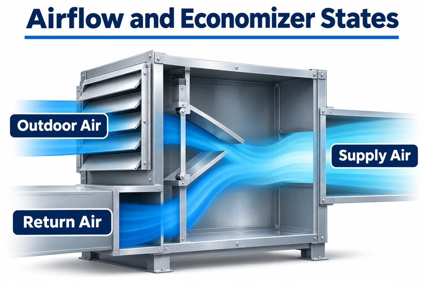
An economizer alters where air enters and leaves the mixing section. The release pattern when the fan is off and the outdoor-air damper is parked can differ from that at low fan speed with minimum outdoor air or during high outdoor-air operation. During a transition, the controller’s requested damper position and the physical position can also differ. If a unit has a return fan or powered relief, the pressure field can change again. Record which devices are present in every test configuration.
Evaluate the path to the sensing inlet separately from the effectiveness of the resulting mitigation airflow. The former concerns transport before the RDS responds. The latter concerns what the appliance actually does after detection. For example, normal airflow may carry a release past the sensor during one operating mode while the mitigation airflow uses another fan command or damper position. Trace the measured response from stimulus to the physical actions in the intended configuration.
In an engineering run, capture the fan’s operating state, damper command and observed position, filter condition and test configuration alongside the sensor event. Log the data on a common timebase. If only one signal is available, identify which step of the sequence it actually represents. An economizer command, a proving input and direct damper observation answer different questions. Compare tests made with the intended access panels and specified setup so an instrument cable or temporary opening does not change the flow path being evaluated.
Qualify the installed assembly for rooftop exposure
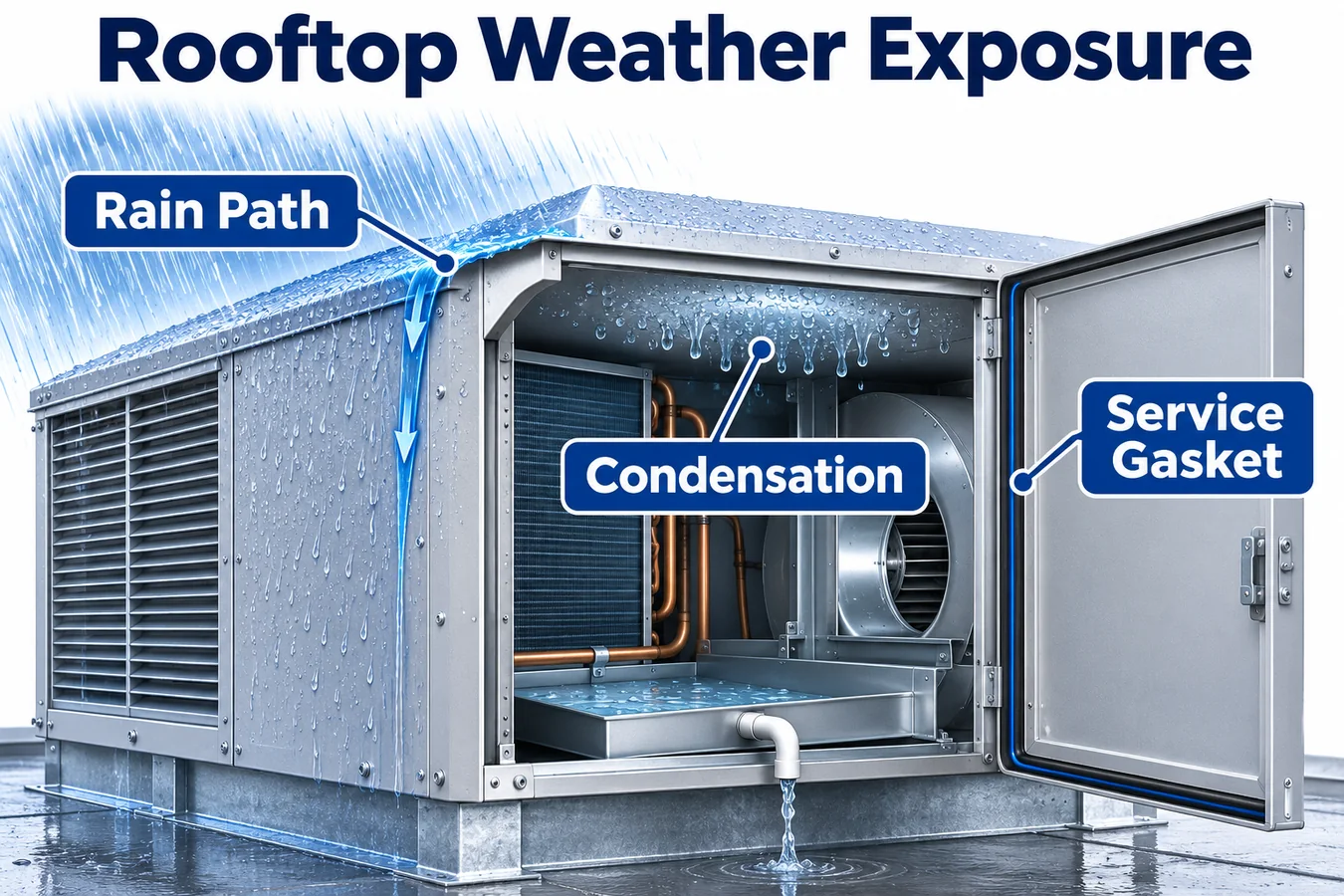
Define exposure where the sensor sits. A weather-resistant rooftop cabinet may enclose sections that cycle through condensation, experience water during service or collect dirt around a drain pan. A module mounted near a coil can see a different thermal and moisture history from the main control board. Document those differences and convert them into test conditions for the complete sensor assembly, including its bracket, harness, enclosure and inlet protection.
Check whether the mounting geometry provides drainage around the sensing inlet in the final unit orientations. Review nearby water paths after coil wash and during condensate production. A shield or screen may address droplets and dirt while also affecting how quickly the gas reaches the sensing element. If engineering adds a shield after a weather test, recheck the applicable transport evidence with the production shield installed. Record what environmental conditioning preceded the response test and whether the assembly was allowed to dry or stabilize beforehand.
Tie the qualification specimens to production process controls. For example, if a foam strip keeps splash away from the inlet, the drawing needs a position tolerance that remains achievable across assembly stations. If the harness routing keeps a drip loop below the connector, show the clip and service replacement path. Where rooftop exposure has a seasonal pattern, describe the order of stresses being represented so the laboratory can reproduce the same sequence.
Turn detection into an explicit controls sequence
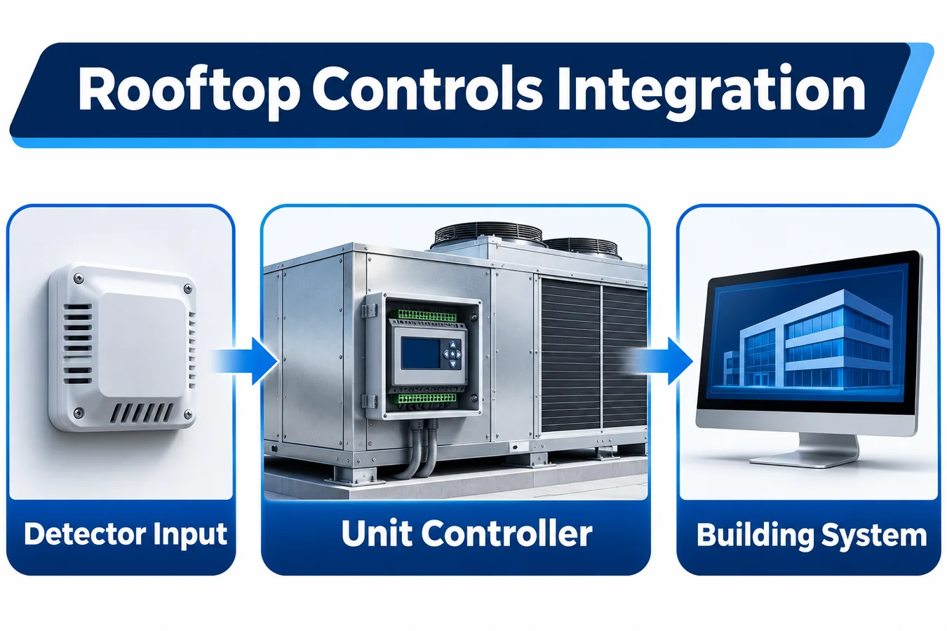
Document the path from the sensor to the local controller and then to each output credited by the OEM evaluation. Identify message or discrete state definitions, power and reference requirements, controller revision, and how a unit distinguishes a valid event from a sensor fault or lost communication. Give each state an observable result, such as a controller log entry and the expected state of an output. Define what evidence demonstrates a commanded action and what establishes that the appliance performed it.
Put normal demand, a detection event, a sensor fault, power interruption and recovery in a state table. If the unit coordinates with external controls, identify who owns each command and how the OEM sequence interacts with other documented priorities. A building management system may display an event for operators while the equipment implements the evaluated response locally. That distinction belongs in the wiring diagram and in the release test so a project does not inadvertently depend on an optional communications gateway.
Specify which log fields a service technician can use to reconstruct the sequence. A useful record identifies the unit, the sensor channel, firmware and configuration, the initial operating state, the state transitions, and the final disposition. If the controller stores only the newest event, a test engineer needs an external record for qualification. For dual-circuit units, distinguish circuit identifiers and sensor identifiers even if the appliance response to a detection is common to the whole unit.
Analyze dual-circuit coverage from the source outward
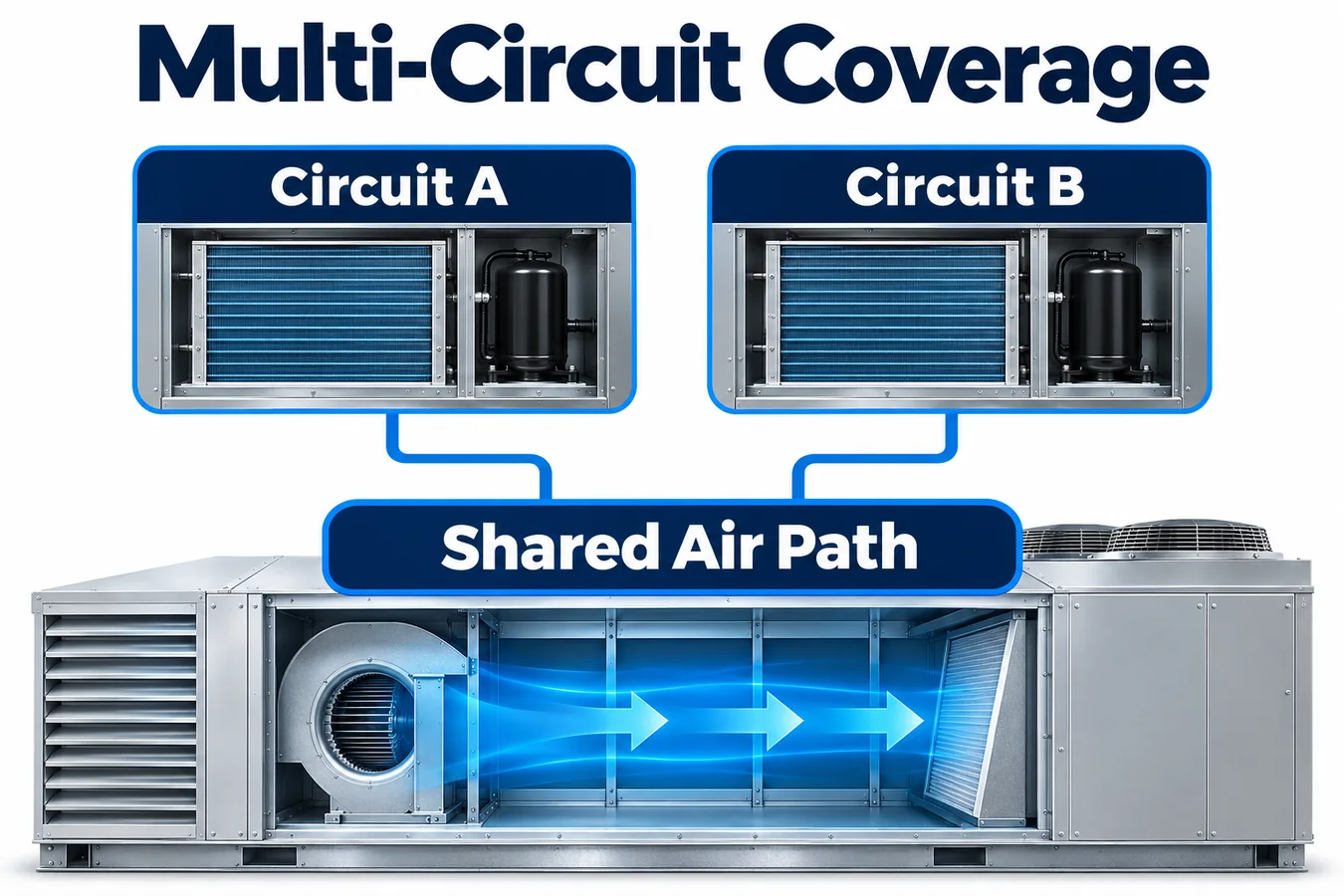
Two circuits can serve a common coil face, occupy separate portions of a coil bay or use different tube routes around the same cabinet. Compare their potential release locations relative to the drain-pan shape and pressure field. A single shared air path can support a common sensing strategy only where the transport and response evidence covers the relevant source locations and operating conditions. Where pockets or airflow split the paths, compare candidate placements and sensing architectures under the OEM evaluation plan.
Add dependencies shared by the circuits. Both may rely on the same fan, control supply, harness branch or communication bus. If a two-sensor design shares a supply, explain how the equipment identifies an interruption that affects both channels. If a sensor channel can be swapped in production, verify that the controller reports the intended location and that the installation drawing prevents or detects the swap. Separate coverage questions from availability questions in the review record.
For models with staged cooling, compare the scenarios that are distinct before any detection. One active circuit may alter the fan state or create a different local thermal condition while the other is idle. Determine whether those states can change transport and give each significant state a test ID. Also distinguish the source of the simulated release from the action taken on equipment. A test case can represent a release from Circuit B even when the applicable equipment response is common to Circuits A and B.
Use a configuration matrix to decide where evidence can transfer
The example assumes a light commercial product line with a base downflow unit, an optional economizer, a horizontal discharge conversion and a larger dual-circuit cabinet. It assumes a common controller family and a common proposed sensor family. Every test disposition in the matrix is hypothetical. The equipment drawings, certification review and approved test plan govern actual release decisions.
| Example build | Material difference | Evidence to request | Family decision |
|---|---|---|---|
| S1 base downflow | One circuit and fixed outdoor-air configuration | Representative release tests, installed exposure and complete controls sequence | Baseline group |
| S1 with economizer | Outdoor, return and relief paths can change | Trace release scenarios across representative damper and fan states and confirm output behavior | Transfer unchanged electrical evidence and review airside evidence |
| S1 horizontal conversion | Air openings and collection geometry may change | Check approved conversion drawing, sensor placement and complete installed test cases | Separate geometry case pending demonstrated equivalence |
| S2 larger dual-circuit | Different coil and release locations with shared controls | Include a scenario set for each circuit, shared dependency checks and complete unit response | Distinct qualification group unless evidence supports a narrower split |
| S2 revised drain pan | Shape and wetting near inlet can change | Compare controlled drawings, wetting tests and transport evidence around the revised area | Engineering review and affected retest before release |
Add the test report, specimen build and approval owner to the live version of the table. Track provisional carryover separately from verified carryover. If a horizontal conversion is restricted to a subset of cabinets, prevent sales configuration from offering it on a row that has no supported installation path. The matrix is useful to production only when the order code maps to the validated group.
Walk an example through a change review
Suppose the larger unit shares a sensor family and controller with the base unit. The first build review finds that its second circuit returns through a different end sheet and the larger drain pan adds a raised rib. With the fan idle, the rib may separate the proposed sensor inlet from one release path. With airflow, the return duct may carry the release toward the fan instead. The review records each path as a test hypothesis and assigns the second circuit its own source cases.
Engineering compares an alternate bracket, a revised inlet location and a two-channel configuration. Compare these options by asking which closes the coverage gap in the documented operating states, which exposes additional control dependencies, and which technicians can restore during routine coil service. An alternate bracket can be inexpensive to manufacture yet costly to validate if its installation tolerances allow the inlet to sit on either side of the rib.
Assume the comparison selects an alternate mounting location and retains the proposed sensor family. The decision record links the bracket drawing and orientation to the affected serial ranges and identifies which base-unit evidence still applies. The service instructions and parts lookup now distinguish the larger build by the installed bracket and harness as well as the module. If the alternate position later becomes common across more variants, repeat the inheritance review with the revised drawings and evidence.
Qualify component behavior and installed response
Set up the qualification package as a chain of evidence. The component portion identifies the exact module build, refrigerant configuration, environmental history, communication behavior and measurement method. The integration portion connects a specified release scenario to a sensor indication and the appliance response, including verified outputs where the evaluation credits them. The production portion confirms that the assembly tested in the lab can be built repeatedly with the correct components and configuration.
Report where the tests begin. A simulated sensor input can verify control mapping and command handling. An installed release test exercises gas transport and sensing under the approved method. A manufacturing electrical check can detect a wiring error or missing module. Record those boundaries separately in the evidence index so a control simulation does not get counted as a transport demonstration or a connectivity check as proof of the whole mitigation chain.
Make failures actionable by capturing the intermediate observations. If the controller responds but a fan does not run as expected, the unit record should help separate a command problem from a drive, power or feedback problem. If the sensor response varies between matched runs, compare the specimen’s panel seal, airflow state, moisture exposure and module configuration before concluding that the sensing element explains the difference. Use the approved OEM test procedure and acceptance criteria for the exact equipment. UL Solutions overview of RDS evaluation requirements
Make field and factory records agree
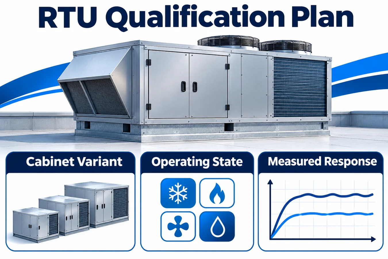
Connect the serial record to a service-readable equipment identifier, the sensor assembly part number, controller configuration and approved physical mounting instruction. Identify parts that remain on the unit during replacement and parts that travel in a service kit. If two generations have the same connector but different controller behavior, split the lookup so the serial range resolves to the correct combination. Also show harness routing and clip positions in a photograph or drawing with enough cabinet detail for a technician to orient it.
When a complaint arrives, record the fan and economizer states if available, any recent service to the coil or drain pan, the installed part identity, and the controller’s event history. Keep the as-found evidence associated with the serial number before replacing a suspect component. A recurrence across identical pans or a particular harness routing can reveal a shared production issue that a collection of unrelated sensor returns would obscure.
Release replacement parts with the same discipline as production parts. If a supplier changes module firmware or a component of the inlet assembly, the OEM should link the proposed substitution to affected qualification groups and obtain the appropriate review before expanding applicability. Add any required post-replacement checks to the instructions and preserve evidence of the completed check in the service record.
Select representative units and retain the comparison evidence
A qualification group usually needs more than a list of models and a representative selected by capacity. Write down which physical feature makes each chosen build a useful representative. For the example family, the largest cabinet might have the longest path from a specific release source to the proposed inlet. The shallowest cabinet might place the inlet closest to a wet surface. Those are different effects and may call for different specimens. Test selection should include both where they can change the outcome.
Use tolerance drawings to distinguish a nominal location from its expected production range. Compare the tube and bracket locations, panel and pan fit, harness reach and inlet clearance at the edges of those ranges. Where feasible, record the as-built dimensions of the qualification unit and link them to the tolerance assessment. A nominal build can establish a baseline. Evidence for an extreme assembly condition should identify what was actually varied and how the test team verified the configuration.
Make the selected operating conditions reproducible. If the fan was in a low demand stage, record the command and measured state. If the return path used a project-specific curb or adapter, explain whether that geometry is part of the claim or a condition selected only for the experiment. Document fixtures, instrumentation and any temporary panel changes alongside the result. When the manufacturer subsequently qualifies an accessory, this detail helps reviewers decide whether the accessory changes conditions that the original evidence covered.
Maintain a short register of open cases at design release. Each entry should identify a proposed model or option, the evidence that is missing, the assigned decision owner and the effect on ordering or service. For example, a design team might release the baseline cabinet and defer the horizontal conversion while it resolves a revised pan. That decision belongs in both the configuration record and the order rules so units cannot be built against a claim still under review.
When a future model shares the same controls but changes the air path, the register makes the reuse boundary visible. The team can reference the existing controller evidence, select the new transport cases and keep both sets linked to the serial ranges they support.
Candidate module for OEM review
Winsen’s ZRT512E-R454B candidate refers to the manufacturer’s ZRT512E R454B and R32 series. Request the exact suffix, refrigerant configuration, connector and harness drawing, protocol definition, firmware identification and supporting documentation for the configuration under review. Treat the pictured module as a candidate for the OEM’s electrical and mechanical evaluation. Applicability belongs to the exact equipment and module combination released by the OEM. Winsen ZRT512E series product profile

Frequently asked questions
Does an outdoor rooftop cabinet eliminate the integral RDS question?
Start with the exact appliance documentation and certification scope. A rooftop cabinet can contain a coil and supply or return path connected to indoor spaces alongside sections open to outdoor air. The evaluated release and transport scenarios establish which portions are relevant for the specified equipment. UL Solutions RDS inspection guidance
Does each circuit need its own sensor?
Sensor count follows the evaluated coverage and system architecture. Identify each circuit’s relevant sources and compare the routes they have to a proposed inlet under the affected operating states. Where two channels are used, verify channel identity and the response to lost communication as well as the coverage.
Can an approved sensor position transfer from a base cabinet to an economizer model?
Review the mounting and air path changes against the evidence for the base cabinet. The option may preserve the physical bracket while changing the pressure field, paths around the damper or operating fan state. Record the basis for any transfer and close the remaining evidence gaps before the option joins the same qualification group.
What changes when the replacement module uses the same connector?
Matching connectors can simplify a mechanical check. Confirm the approved part applicability, electrical assignment, configured refrigerant, firmware compatibility and diagnostics. Where the OEM’s instructions require a replacement verification step, record its result with the unit serial number.
Which evidence belongs in a procurement review?
Request the supplier’s exact assembly and revision identifier, the supported refrigerant configuration and interface, the drawings that constrain the mounting, the qualification scope, and the change notification process. Link each item to the OEM configuration ledger. A purchase specification based only on the series name makes it difficult to tell whether a shipment matches the tested assembly.
Request an OEM evaluation package
Send the target model and serial families, refrigerant circuit maps, cabinet sections, mounting orientations, economizer options and controls interface to the OEM integration team. Include the proposed service replacement strategy and the certification scope for the intended market. Ask the module supplier to identify the exact candidate configuration and provide its controlled documentation. Use the first review to assign ownership of the model-family matrix, confirm the evidence required for each group, and agree on samples and build revisions for the next test round.
