
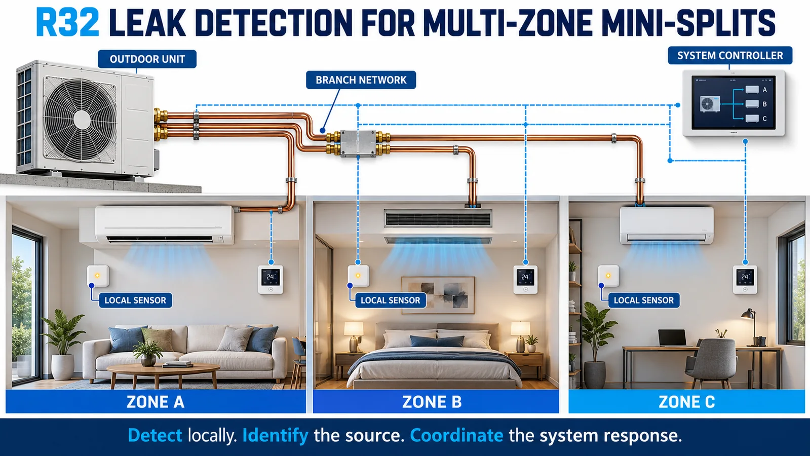
A multi-zone mini-split connects several occupied spaces to one outdoor refrigerant circuit. That creates a design problem that a single “system sensor” cannot solve by itself: a leak may occur at one indoor coil, while refrigerant inventory, communications and mitigation decisions are shared across the system. Effective R32 leak detection for a multi zone mini split therefore needs local awareness, preserved zone identity and a coordinated response.
This guide is for OEM, VRF and controls engineers. It describes an architecture and validation method, not a universal sensor position, alarm threshold or valve sequence. The evaluated equipment design, current standards, certification requirements and manufacturer instructions govern the final implementation.
Separate the three system boundaries
Begin with three drawings. The refrigerant-circuit boundary shows compressors, branch devices, pipes, indoor coils, service valves and the charge that can reach each branch. The occupied-space boundary shows the room served by each indoor unit, openings, adjacent spaces and relevant room volume. The detection-and-control boundary shows sensors, controllers, networks, power supplies, outputs and actuators.
These boundaries rarely match. Two indoor units may share refrigerant inventory but expose different rooms. One supervisory controller may receive both signals, yet a communication break can separate their safety functions. Mapping the boundaries prevents a system-level alarm from hiding the local question: which occupied zone is affected, and what response is available there?

Treat each indoor unit as a local detection problem
For design purposes, start with each indoor unit as an independently exposed zone. Map credible release locations around its coil, joints, distributors and branch connections. Then evaluate the installed orientation, casing, drain pan, louvers, fan states and room interfaces that shape the gas path.
A local detector should sample the concentration field produced by that specific equipment, not merely the general room air. Wall-mounted, ceiling cassette, concealed ducted and floor-console units have different pockets and discharge paths. Use the approved product geometry and production-intent parts when selecting candidate locations.
This does not mean that every room always needs the same number of sensors. It means local coverage must be demonstrated before a supervisory architecture is credited.
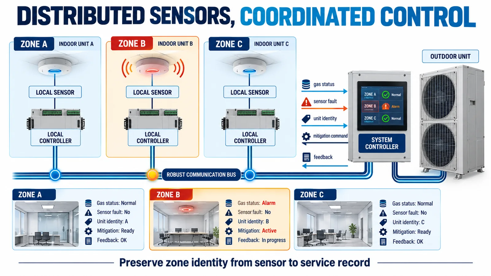
Preserve zone identity from sensor to action
The controller should know which detector generated an alarm or fault. Avoid combining several indoor-unit channels into an anonymous contact unless the certified safety concept explicitly accepts that loss of information. Address, configuration and unit identity should remain traceable through commissioning and service replacement.
A practical point list includes detector signal or state, sensor health, communication health, indoor-unit operating state, commanded mitigation, actuator feedback and a latched event record. The installer should be able to prove that the physical sensor in Zone 3 is mapped to the Zone 3 record and response—not just that “an alarm occurred somewhere.”
Decide where the safety decision lives
The primary decision can be local to the indoor unit, supervisory, or layered. A local controller can respond even when the building network is unavailable. A supervisory controller can coordinate outdoor-unit and branch actions. A layered design can provide local protection while sharing status and issuing system-wide commands.
Whichever architecture is chosen, document timing, priorities and authority. Define what happens if the local alarm arrives while the supervisory controller is rebooting, if two zones disagree, or if an older controller receives a message from a replacement indoor unit. Safety behavior should not depend on a cloud service or an undocumented automation rule.
Coordinate mitigation without assuming every zone needs the same action
Depending on the evaluated equipment, an alarm may command circulation, stop a compressor, change indoor fan operation, close an evaluated valve, activate external ventilation or provide notification. The correct response is equipment-specific. A blanket rule such as “turn every fan on” can be wrong if a fan transports refrigerant to another space; “turn everything off” can be wrong if circulation is part of the certified mitigation.
Create an alarm-action matrix for each indoor-unit type and operating state. Include the initiating zone, other occupied zones, outdoor unit, branch devices and external ventilation interfaces. Record both the command and confirmation that the intended state was achieved.
Evaluate isolation as a refrigerant-inventory problem
Multi-zone systems may use shutoff or branch isolation devices as part of the safety design. A valve symbol alone is not proof of protection. Determine how much refrigerant remains between valves, which outdoor and indoor volumes can still discharge, valve closing behavior, leakage across the seat, loss-of-power position and whether position feedback is safety-relevant.
An isolated branch may still contain enough refrigerant to matter to its occupied space. Conversely, closing one branch may change pressure and flow in another. Validate the complete sequence using the charge and pipe arrangement allowed by the equipment program. UL Solutions notes that multi-indoor-coil systems commonly involve shutoff-valve considerations; final requirements remain tied to the applicable listing and instructions.
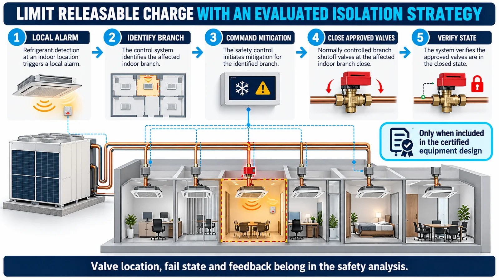
Make communication and power failures deterministic
Every link in the chain needs a defined failure response: sensor-to-indoor controller, indoor-to-supervisory network, controller-to-outdoor unit and controller-to-valve or ventilation interface. Decide how loss of valid data differs from a confirmed gas alarm and how each state is annunciated.
Specify timeouts, startup supervision, stale-data detection, message integrity, address conflicts and recovery. Consider separate local and network power loss, brownout, controller reboot and interrupted firmware update. A communication fault should not silently become a healthy zero reading, and automatic recovery should not clear a latched condition before the equipment-defined criteria are met.

Handle simultaneous and cascading events
Test beyond a single clean alarm. Two sensors may alarm because one release reaches connected spaces, because two branches are affected, or because a common power or communications problem produces multiple faults. The control logic must distinguish alarm, fault and unavailable states without averaging away a local hazard.
Build scenarios for local alarm, simultaneous alarms, detector fault, network loss during alarm, actuator failure, power interruption and recovery. Define which actions remain local and which require coordination. Event timestamps help engineers reconstruct the sequence, but time synchronization itself should not be a single point of failure for the protective action.

Engineer commissioning around identity and response
Commissioning should prove more than electrical continuity. Verify the installed sensor part and orientation, inlet clearance, harness, address, firmware, indoor-unit mapping, alarm path, actuator commands, feedback and annunciation. Use the manufacturer-approved functional method; do not instruct field personnel to create an uncontrolled refrigerant release.
Retain a record for every indoor unit. Service replacement must restore the qualified part, location, configuration and identity. If a replacement controller assigns addresses automatically, include a controlled check that room labels and network objects still correspond.
Validate the system as well as each indoor unit
First establish local coverage with controlled releases at credible sources and all required fan, louver and environmental states. Then validate the integrated system with the permitted combinations of indoor units, branch devices, pipe lengths, charge, network topology and firmware.
The matrix should include normal operation, startup, standby, defrost or heating states when applicable, alarm, sensor fault, communication loss, mitigation feedback and recovery. Record reference concentration, detector response, commands and physical actuator states. Repeat limiting cases across manufacturing and environmental corners.

Control variants and future changes
One outdoor platform may support many indoor-unit families. Keep a compatibility table linking each indoor model, sensor variant, bracket, controller version, branch device and validated configuration. Block unsupported combinations in selection tools and commissioning software where practical.
Changes to coil geometry, casing openings, louvers, drain parts, fan curves, valves, charge limits, network timing or firmware can affect the safety case. Apply an impact review and focused retest where justified. Do not assume that a new indoor unit inherits evidence because it uses the same connector.
Integrate a controlled sensor interface
윈센의 ZRT512C-A refrigerant detection module is listed in the official WooCommerce product data as an NDIR module for R32, R454B and R290, with PWM, RS485 and UART interface options. Confirm the exact model, refrigerant calibration, electrical limits, protocol, response behavior, dimensions and qualification evidence against the current controlled datasheet before design release.

Continue with R32 sensor integration in wall-mounted mini-splits,,, R32 sensor location and airflow geometry,,, R32 leak-alarm control sequencing 그리고 orientation-dependent sensor placement.
What to send for a multi-zone design review
Provide the refrigerant and maximum charge, outdoor and indoor-unit models, room and circuit boundaries, pipe and branch layout, installation orientations, controller and valve architecture, interfaces, alarm target, environment, annual volume and certification market. Winsen can review candidate sensing interfaces and the system validation matrix.
Contact Winsen for a multi-zone R32 sensing review.
