UL 60335-2-40 Refrigerant Detection Sensor Requirements
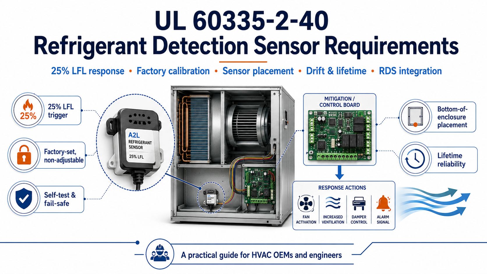
If you manufacture, specify, or integrate A2L HVAC equipment, the most important point is this: under UL 60335-2-40, the refrigerant detector is not treated as a generic accessory. It is part of a refrigerant detection system (RDS) that includes the sensor, control logic, mitigation response, installation method, and long-term reliability evidence. UL describes the standard as the U.S./Canada binational requirement for heat pumps, air-conditioners, and dehumidifiers, and says the fourth edition refined leak-detection requirements to improve robustness, reliability, and evaluation of drift over life.What UL 60335-2-40 is actually regulating
UL 60335-2-40 is not just a “sensor standard.” It is the product-safety standard for certain HVAC appliances, and the refrigerant detector requirements sit inside a broader safety model that also covers charge limits, room-volume assumptions, ignition-source control, and mitigation actions. UL says refrigerant leak detection systems are required to have both sensors and control logic electronics that activate the evaporator fan and use circulated air to quickly disperse and dilute refrigerant in the event of a leak. UL also says the charge-limit approach includes a safety factor of 4 tied to the minimum occupied room volume.So when buyers ask about “sensor requirements,” the technically correct answer is: UL 60335-2-40 is evaluating the whole detection-and-response chain, not just whether a probe can see gas in the lab.The single most important requirement: 25% LFL
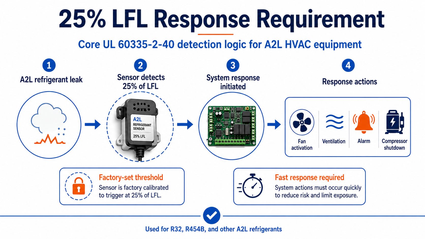 The core trigger level in current UL guidance is 25% of the lower flammability limit (LFL) of the refrigerant. UL says the rewritten Annex LL in the fourth edition clearly establishes that when the refrigerant detection system senses 25% LFL, it must initiate a system response to mitigate the hazard. UL also explains that earlier language tied response to 100% LFL-or-lower ranges, while the updated CRDs explicitly define response around 25% LFL because 100% LFL is too high to manage fire risk safely.TI’s 2024 A2L design note gives a practical engineering version of the same principle, stating that the refrigerant detection system shall make output within 30 seconds of direct exposure to 25% LFL. UL’s 2024 code-authority article adds a field-facing interpretation, saying an integral RDS is typically designed to initiate mitigation within 15 seconds of detecting 25% LFL or moreו
Why 25% LFL matters
This threshold is important because it pushes the system to detect early and mitigate before refrigerant concentration gets close to an ignitable mixture. In practical HVAC terms, that means the detector is part of a prevention strategy, not just a maintenance notification tool.What counts as the “refrigerant detection system” under UL 60335-2-40
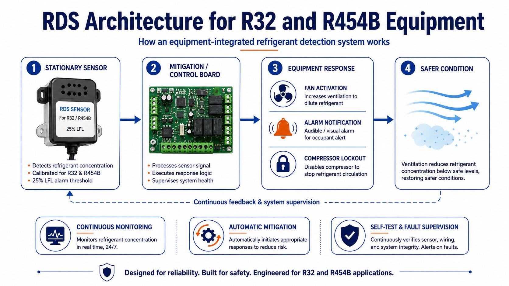
UL defines an integral RDS as a system using one or more stationary sensors to detect a refrigerant leak at a specified concentration and automatically initiate one or more mitigating actions. When required, UL says this integral RDS is evaluated as part of the HVAC equipment certification and must be installed within the HVAC equipment according to the manufacturer’s installation instructions.That means the compliant system usually includes:- a stationary refrigerant sensor,
- control or mitigation logic,
- mitigation outputs such as fan activation,
- and fault/alarm handling.
Calibration requirements: factory-set, sealed, and not field-adjustable
One of the most important practical requirements is calibration control. UL’s published guidance states that the refrigerant leak detector set point is factory set and sealed, with no field adjustment permitted. UL’s updated-requirements article also says the fourth-edition framework clearly defines calibration, and the comparison table states that refrigerant detection systems shall be preset and calibrated from the factory for the refrigerant used, the preset level shall not be adjustable, and recalibration other than zero-point self-recalibration is not allowed.For OEMs, this has a direct design implication: do not build your compliance strategy around a field technician “tuning” the threshold later. The intended concentration level and refrigerant target need to be established in the listed design.Drift, deviation, and lifetime evidence are part of the requirement
UL’s fourth-edition guidance places unusual emphasis on drift, deviation, and long-term sensor reliability. UL says Annex 101.DVM was revised to include requirements for deviation and drift over the lifetime of the refrigerant sensor, and that it now describes acceptable paths for providing evidence supporting the claimed sensor life. UL also explains that the CRDs introduced allowances and evaluation methods specifically to address long-term reliability.This matters because HVAC equipment may stay in service for years in heat, humidity, dust, oil mist, and vibration. Under UL 60335-2-40, the compliance conversation is not only “does the sensor work on day one?” but also “can the manufacturer substantiate that it remains reliable over its claimed life?”Self-test and fail-safe behavior
UL’s updated comparison table also highlights self-test and fail-safe concepts. It states that the refrigerant detection system shall include a means for self-testing to determine whether a sensor or sensing-element malfunction has occurred, and further says the design is intended to fail-safe and engage an appropriate system response.That means a compliant design is not only watching for refrigerant. It is also watching itself. For a buyer, that is a major distinction between a consumer-style gas alarm and an appliance-integrated detection system intended for safety-critical action.Placement requirements: sensor location is not arbitrary
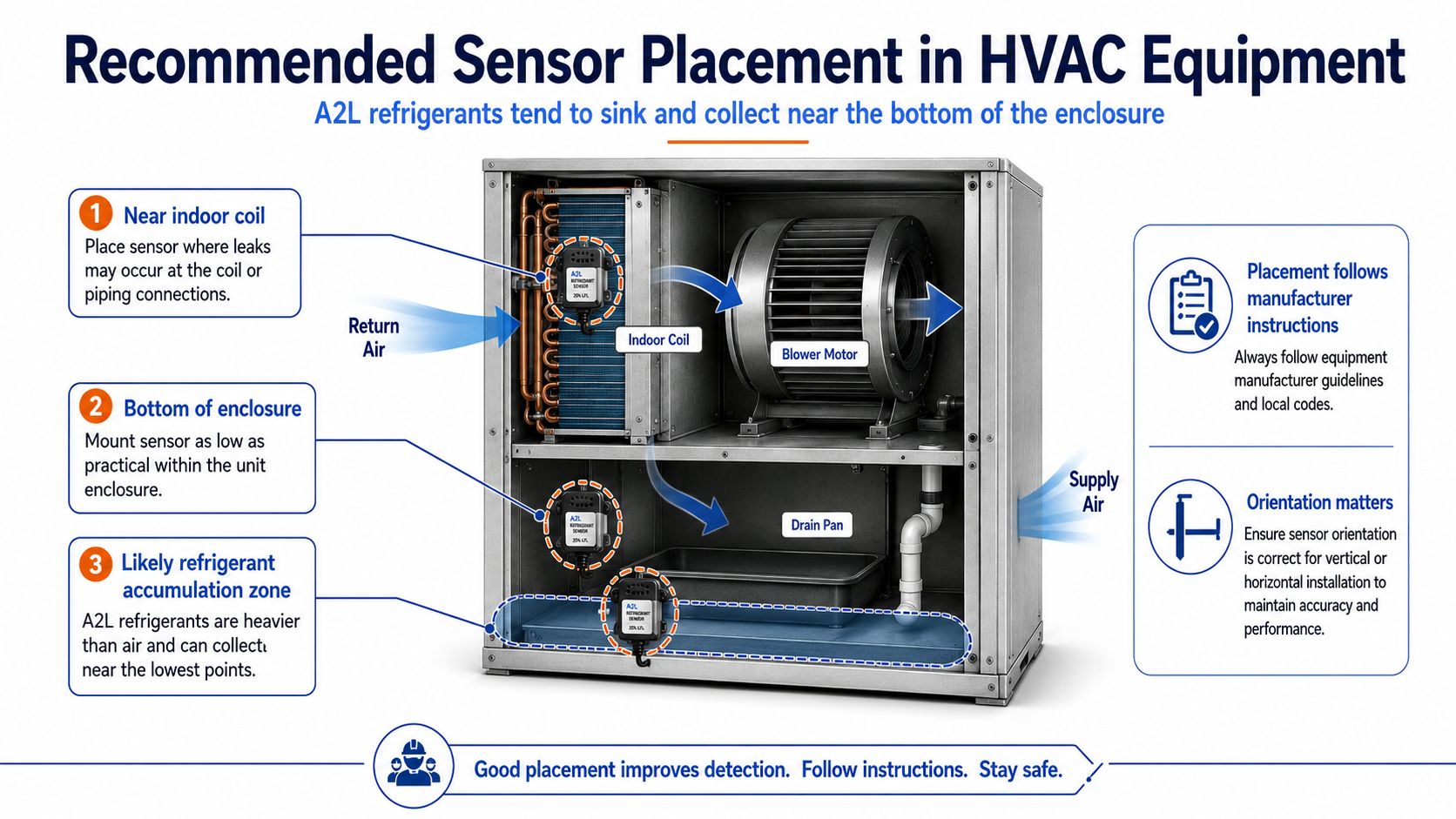
Sensor placement is one of the most operationally important UL 60335-2-40 requirements. UL’s 2024 code-authority guidance says A2L refrigerants are heavier than air, so installation instructions will typically specify locations where leaked refrigerant is likely to sink and collect. UL says this is most often near the indoor coils toward the bottom of the enclosure, and systems with multiple indoor coils will typically use multiple sensors.UL also notes that field verification or relocation may be needed depending on the installed orientation of the equipment, because up-flow, down-flow, or horizontal configurations can change where refrigerant accumulates.Factory-installed or field-installed?
UL says both approaches are allowed. The integral RDS may be factory-installed אוֹ field-installed, but the installation instructions determine whether the listed equipment requires an RDS, which specific RDS is permitted, and how it must be installed.That means “field installable” does not mean “installer can use any sensor they want.” It means the listed equipment and its instructions control the allowable hardware and the installation method.When an RDS is typically required
 UL says the exact determination is made under detailed criteria in UL 60335-2-40 and the manufacturer’s installation instructions, but gives a general field rule: expect an integral RDS to be required for HVAC equipment with over about 2 pounds of charge for nonfixed factory-sealed equipment אוֹ over about 4 pounds for other types. UL’s 2025 installation checklist repeats the same “typically required” guidance.This is useful as a screening rule for content and sales discussions, but it is still not a substitute for the equipment’s actual listed instructions.
Labeling and identification
UL’s older but still useful safety article states that detector markings identify the manufacturer and refrigerants used, and UL’s 2025 standards-update page notes added clarification for labeling requirements for appliances containing flammable refrigerants.For buyers and OEMs, that reinforces another practical point: a compliant refrigerant detector is supposed to be clearly associated with the specific refrigerant/application, not treated as a generic combustible-gas device with vague compatibility.What HVAC OEMs and buyers should specify
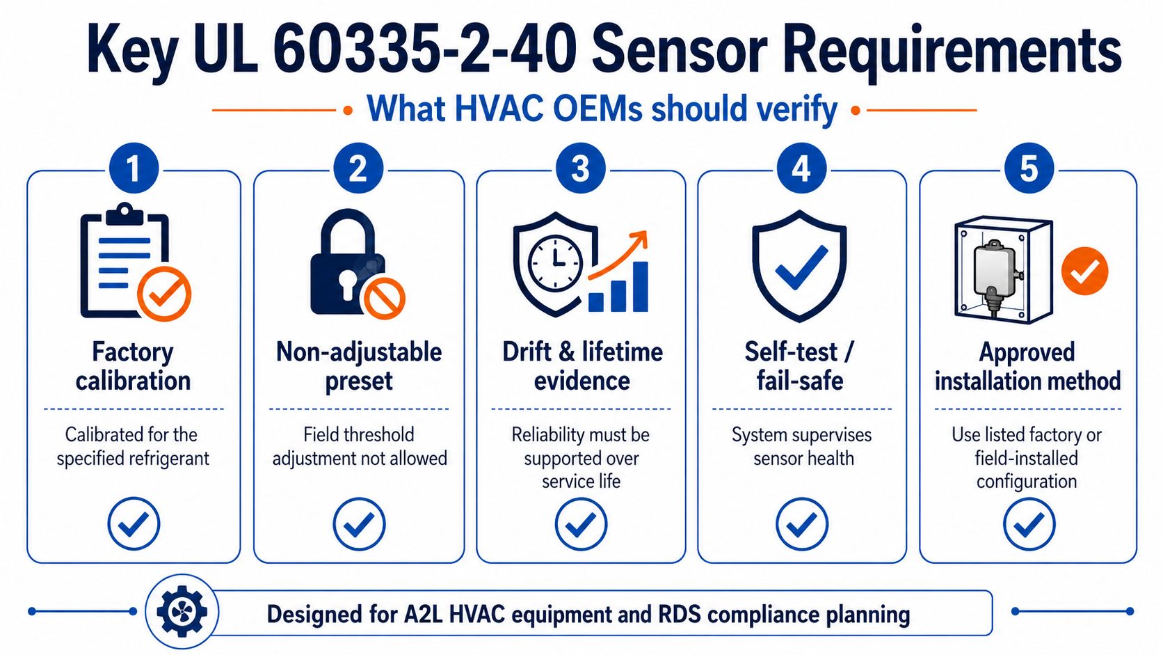
 If you are writing a spec sheet, buying guide, or product page around UL 60335-2-40 sensor requirements, these are the most important items to define:1. Refrigerant-specific calibration
The detector should be factory-calibrated for the refrigerant used in the appliance, with nonadjustable preset level behavior.2. 25% LFL response logic
The product should clearly state how it responds at 25% LFL, since that is the central trigger point in UL’s current requirements language.3. Response-time behavior
UL field guidance and TI design guidance both point to fast action after 25% LFL exposure.4. Drift/life evidence
A serious OEM sensor should have documented support for deviation, drift, and lifetime reliability.5. Placement instructions
The detector should come with installation guidance that matches the equipment orientation and leak-accumulation behavior.6. Fault supervision and fail-safe behavior
The sensor system should include self-test and defined safe response for malfunction.
If you are writing a spec sheet, buying guide, or product page around UL 60335-2-40 sensor requirements, these are the most important items to define:1. Refrigerant-specific calibration
The detector should be factory-calibrated for the refrigerant used in the appliance, with nonadjustable preset level behavior.2. 25% LFL response logic
The product should clearly state how it responds at 25% LFL, since that is the central trigger point in UL’s current requirements language.3. Response-time behavior
UL field guidance and TI design guidance both point to fast action after 25% LFL exposure.4. Drift/life evidence
A serious OEM sensor should have documented support for deviation, drift, and lifetime reliability.5. Placement instructions
The detector should come with installation guidance that matches the equipment orientation and leak-accumulation behavior.6. Fault supervision and fail-safe behavior
The sensor system should include self-test and defined safe response for malfunction.שאלות נפוצות