
ZRT512 Series
Refrigerant Detection Module
RS485 refrigerant detection module using Modbus RTU communication for R290 monitoring and equipment integration.
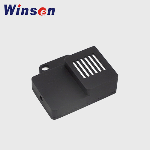
Compact refrigerant monitoring with industrial RS485 integration.
The ZRT512 series provides an infrared refrigerant detection platform with Modbus RTU communication, configurable device address, fault reporting and operating-life monitoring.
Model coding supports different power-supply versions
Power option A uses 5 ± 0.5V, while option B supports 7–32V. Communication code 4 indicates RS485, and gas code R indicates R290.
[email protected] · refrigerantsensor.com

 Scan for
technical support
Model Coding, Product Dimensions and PIN Definition
Model description

| PIN | Wire Color | PIN Description |
|---|---|---|
| 1 | White | RS485-A |
| 2 | Blue | RS485-B |
| 3 | Brown | VCC |
| 4 | Black | GND |
RS485 and Modbus RTU Communication Settings
The ZRT512 series uses RS485 communication. The communication protocol and data format are defined below.
| Physical layer | RS485 |
| Software protocol | Modbus RTU |
| Data byte order | High byte first |
| CRC byte order | Least byte first |
| Data frame | Start bit: 1 bit; data bits: 8 bits; stop bits: 2 bits; no parity |
| Baud rate | 2400 bps (default) |
| Modbus address | 0x01 (default) |
| Supported function codes | 0x03 — Read multiple holding registers 0x06 — Write a single register |
| Supported exception codes | 0x01 Illegal function; 0x02 Illegal address; 0x03 Invalid data value; 0x04 Server-side equipment failure |
Holding Register Map
| Access | Register | Address | Qty. | Data Type | Description |
|---|---|---|---|---|---|
| Read | Sensor module temperature | 0x0114 | 1 | int16 | Measured temperature in °C × 10 (e.g. 210 = 21.0°C). Resolution: 0.1°C. Range: −45 to 130°C. |
| Read | Sensor module humidity | 0x0115 | 1 | int16 | Measured humidity in %RH × 10 (e.g. 305 = 30.5%RH). Resolution: 0.1%RH. Range: 0–100%RH. |
| Read | Coarse sensor dew point | 0x0116 | 1 | int16 | Measured dew-point temperature in °C × 10. Error: ±2°C. Resolution: 0.1°C. Range: −86 to 130°C. |
| Read / Write | Device address | 0x0120 | 1 | uint8 | Modbus slave address. Range: 1–247; default: 1. Soft reset or power cycle is required after a change. |
| Read | Leakage signal trigger threshold | 0x0124 | 1 | uint16 | Gas concentration level that triggers the leakage signal. Resolution: 0.1% LFL (e.g. 251 = 25.1% LFL). |
| Read | Lifespan warning trigger threshold | 0x0126 | 1 | uint16 | Lifespan count that triggers the lifespan warning signal. Resolution: 1 day. Range: 0–65535 days. |
| Read | Lifetime alarm trigger threshold | 0x0127 | 1 | uint16 | Lifespan count that triggers the lifespan alarm signal. Resolution: 1 day. Range: 0–65535 days. |
| Read | Equipment marking | 0x0140 | 10 | string[20] | Device tagging information. |
| Read | Firmware version | 0x014A | 1 | uint8[2] | High byte: major version; low byte: minor version. |
| Read | Gas type | 0x014C | 1 | enum | Gas type configured in the sensor module. 0: default value. |
| Read | Lifespan counter (days) | 0x014E | 1 | uint16 | Equipment lifespan measured in days. Resolution: 1 day. Range: 0–65535 days. |
| Read | Lifespan counter (hours) | 0x014F | 1 | uint16 | Additional hours used with the day counter. Resolution: 1 hour. Range: 0–23 hours. Updated every hour. |
| Read | System uptime | 0x0151 | 2 | uint32 | Device uptime since last reset or power cycle. Resolution: 1 second. Range: 0–4.2 billion seconds. |
Fault Definition
| Bit | Fault | Description |
|---|---|---|
| 0 | Gas concentration exceeds limit | Gas concentration exceeds the supported range. |
| 1 | Temperature value exceeds limit | Detected temperature exceeds the specified limit. |
| 2 | Self-check failed | Internal sensor malfunction. |
| 3 | Low voltage fault | Supply voltage is below the required level. |
| 4 | — | Reserved. |
| 5 | Exceeding lifespan limit | The module has reached its service-life limit of 15 years. |
| 6 | Nearing end of life | The service-life warning threshold has been reached. |
| 7 | Dew point alarm | Dew point is above 40°C. |
| 8–15 | Reserved | Reserved. |
Modbus Sending and Receiving Formats
| Device Address | Function Code | Data | CRC Check |
|---|---|---|---|
| 1 byte | 1 byte | N bytes | 2 bytes |
| Device Address | Function Code | Start Address High | Start Address Low | Register Qty. High | Register Qty. Low | CRC Check |
|---|---|---|---|---|---|---|
| 1 byte | 03 | 1 byte | 1 byte | 1 byte | 1 byte | 2 bytes |
| Device Address | Function Code | Returned Bytes | Register 1 High | Register 1 Low | … | CRC Check |
|---|---|---|---|---|---|---|
| 1 byte | 03 | 1 byte | 1 byte | 1 byte | … | 2 bytes |
| Device Address | Function Code | Register Address High | Register Address Low | Write Value High | Write Value Low | CRC Check |
|---|---|---|---|---|---|---|
| 1 byte | 06 | 1 byte | 1 byte | 1 byte | 1 byte | 2 bytes |
When the write operation is successful, the module returns the original request message.
| Device Address | Function Code | Exception Code | CRC Check |
|---|---|---|---|
| 1 byte | Request function code + 0x80 | 1 byte | 2 bytes |
CRC checksum: CRC-16/MODBUS polynomial x¹⁶ + x¹⁵ + x² + 1.
Precautions and Technical Support
Power Supply
Keep the voltage within the specified range and use a stable power supply. Excessive voltage may damage the module; insufficient voltage may prevent normal operation.
Environment
Avoid prolonged exposure to high temperature, high humidity, strong electromagnetic fields, excessive dust, strong air convection or similar harsh conditions.
Mechanical Handling
Avoid impacts, vibration and dropping. Install vertically with the air inlet facing sideways; in areas where water may accumulate, do not face the inlet or outlet upward.
Zhengzhou Winsen Electronics Technology Co., Ltd.
Tel: +86-371-60932955 / 60932966 / 60932977
Fax: +86-371-60932988
E-mail: [email protected]
Product Website: refrigerantsensor.com