
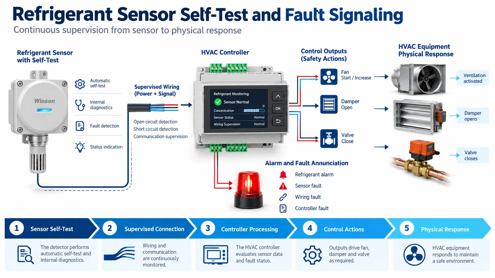
A refrigerant detector is useful only while its information is trustworthy and the HVAC controller knows what to do when it is not. That makes self-test and fault signaling part of the safety function—not optional service features. A detector can remain powered and continue sending a plausible value while an optical path is contaminated, a signal is frozen, a communication frame is stale, or a downstream actuator is unavailable. Conversely, a brief startup or maintenance state can be mistaken for an alarm if the interfaces are poorly defined.
The engineering task is to create a complete diagnostic chain. The detector should identify the internal failures it can actually observe, communicate alarm and fault states without ambiguity, allow the equipment controller to detect missing or stale information, and cause a defined response. The system should also recognize the limits of electronic self-test: energizing an internal diagnostic does not necessarily prove gas can reach the inlet, the sensing chemistry or optics remain sensitive to refrigerant, or the mitigation equipment will operate.
This guide explains how to integrate refrigerant sensor self test fault behavior into HVAC equipment. It focuses on requirements, architecture, state machines, interfaces, verification, and change control. The applicable equipment standard, listing, product instructions, and authority-having-jurisdiction requirements remain controlling.
1. Start with the safety function, not the diagnostic feature list
Before reviewing a sensor’s diagnostic bits, define what the complete equipment must accomplish:
- detect a refrigerant condition within the required system response;
- communicate valid alarm information;
- initiate and verify the specified mitigation;
- detect loss or degradation of monitoring within the required interval;
- enter a defined state when monitoring is unavailable;
- inform service personnel and, if required, remote systems;
- prevent an unauthorized or automatic reset from hiding a continuing hazard.
From those objectives, assign diagnostic responsibilities to the detector, wiring, controller, communication network, power supply, and actuators. A module cannot diagnose an unplugged harness if its only output floats at a normal-looking level. A controller cannot diagnose a frozen digital value unless the protocol provides freshness information or the controller tests for activity.
Create a responsibility table:
| Failure | Detector can observe? | Controller can observe? | Required signal | Required system action |
|---|---|---|---|---|
| internal sensing fault | product-dependent | through fault state | explicit fault | project-defined safe response |
| loss of detector power | sometimes | yes, with interface design | missing/out-of-range | project-defined safe response |
| open or short circuit | interface-dependent | input diagnostics | distinct electrical range | project-defined safe response |
| stale digital data | sometimes | yes | timestamp/counter/timeout | project-defined safe response |
| blocked inlet | rarely proven electronically | not directly | inspection or functional test | maintenance/test action |
| lost sensitivity | limited self-test coverage | not directly | controlled functional test | service action |
| failed fan/damper | outside detector | feedback logic | actuator fault | fallback/annunciation |
Do not mark a row “covered” without naming the mechanism and verification test.
2. Define what self-test can and cannot prove
The phrase “self-test” can refer to very different functions:
- processor memory and watchdog checks;
- supply-voltage monitoring;
- optical source or detector diagnostics;
- internal signal-range checks;
- communication integrity checks;
- simulated alarm output;
- relay exercise;
- end-to-end equipment test command.
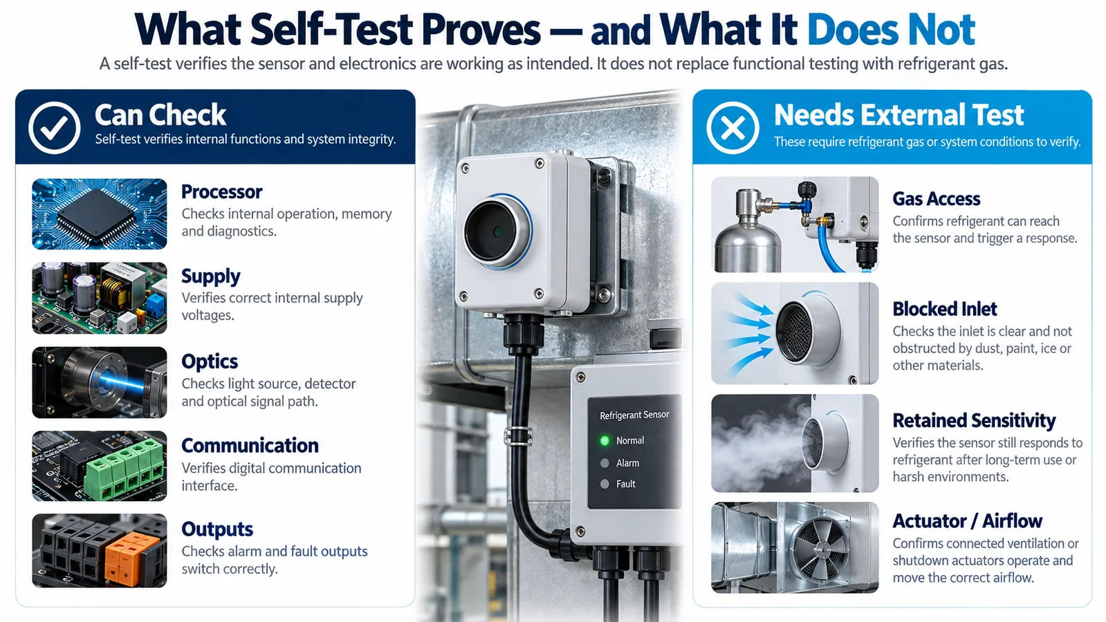
For each self-test, document the stimulus, monitored path, pass criteria, execution interval, output state, and uncovered failure modes. An electronic optical-source test may verify that the emitter and receiver signals change, but it may not prove that external refrigerant can pass through a wet or blocked membrane. A simulated alarm bit may prove the communication and controller sequence, but it does not prove sensor sensitivity.
Use three distinct terms in the documentation:
- Internal diagnostic — checks electronic, optical, firmware, or supply functions inside the detector.
- Output/sequence test — commands an alarm-like output to verify communication and mitigation logic.
- Functional gas challenge — exposes the detector to an approved gas condition to test the gas path and response.
This vocabulary prevents maintenance teams from treating a push-button output test as proof of the entire sensing function.
3. Design startup as an explicit state
Many refrigerant detectors require initialization or warm-up before their output is valid. During startup, the controller should know whether data is unavailable, preliminary, or valid.
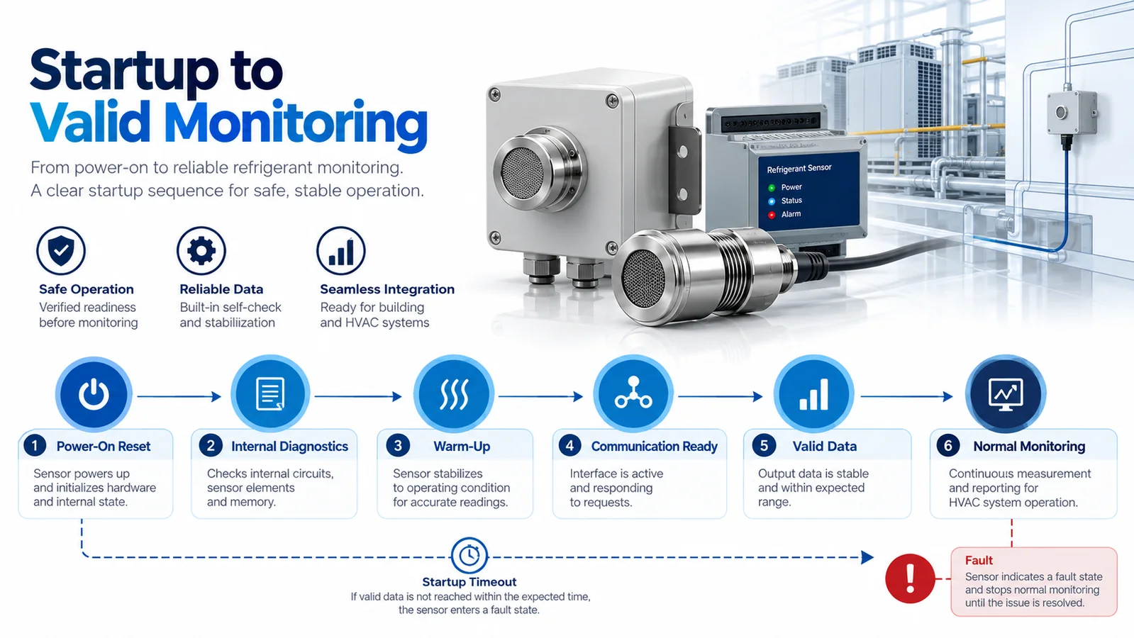
A robust startup sequence includes:
- power-on reset;
- firmware and memory integrity checks;
- supply and internal signal validation;
- sensor stabilization or warm-up;
- communication initialization;
- valid-data declaration;
- transition to normal monitoring.
Define the maximum allowed duration for each applicable state using controlled product information and equipment requirements. If warm-up exceeds the permitted interval, the equipment should declare a fault rather than wait indefinitely.
The control strategy must define whether compressors, heaters, or other functions are permitted before valid monitoring is available. This is a system decision tied to the applicable safety requirements; do not assume a universal answer.
Also evaluate power interruptions. A short brownout may reset the detector while the main controller continues running. The controller should detect the transition and avoid using the last value as though it were current. Record reset reason where practical; repeated resets can indicate power quality or wiring problems.
4. Use continuous diagnostics without corrupting the measurement
Continuous or periodic diagnostics should run often enough to meet the fault-detection objective while avoiding interference with the refrigerant measurement. Potential checks include:
- processor watchdog and program-flow monitoring;
- RAM, flash, or configuration checks;
- supply-voltage range;
- internal temperature range;
- optical source/receiver plausibility;
- baseline or signal-range plausibility;
- ADC or reference checks;
- communication error counters;
- output-driver readback;
- configuration checksum;
- uptime and reset counter.
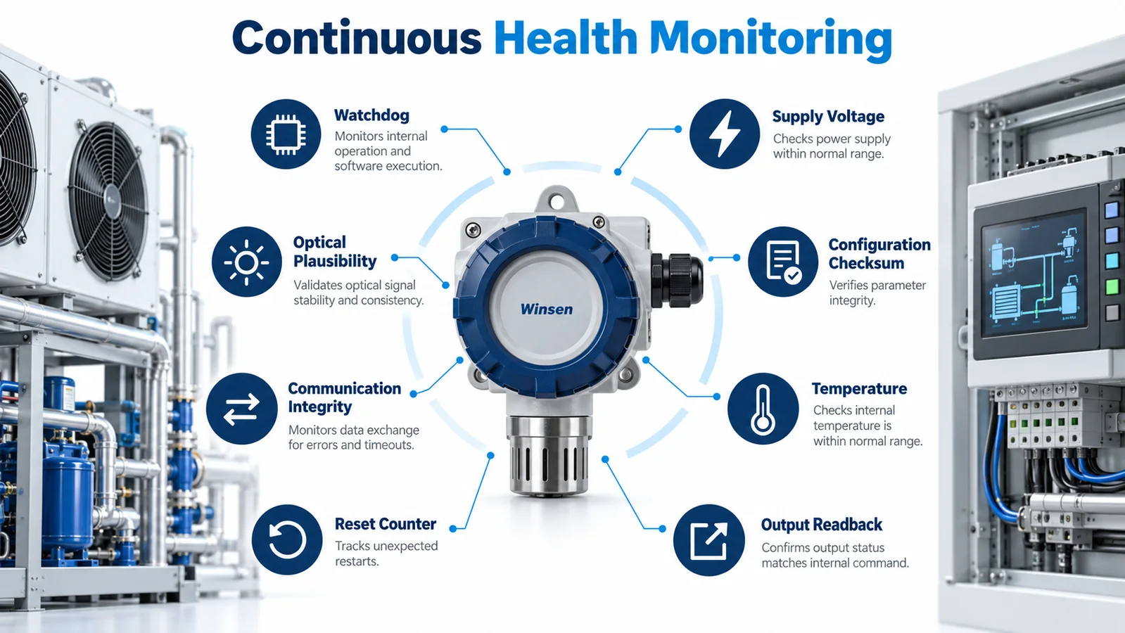
Document whether a diagnostic pauses measurement and how the output behaves during that interval. A controller that sees a repeated “not ready” state needs rules for acceptable duration and frequency. Diagnostic scheduling also belongs in the response-time budget if it can delay a real alarm.
Avoid a single generic fault bit when the protocol can support useful categories. Service teams benefit from distinguishing supply, internal sensor, configuration, communication, and environmental faults. However, the equipment safety response may intentionally group several categories. Keep the service code and the safety state separate.
5. Detect stale or frozen data
A valid-looking concentration value can be dangerous if it has stopped updating. Digital communication should provide a way to determine freshness, such as:
- a message counter;
- a rolling sequence number;
- a sensor timestamp;
- a changing heartbeat;
- periodic status frames;
- a controller timeout based on expected update interval.
The controller must set a maximum acceptable data age and define what happens after it expires. Retries may be appropriate, but they consume time. A gateway or building-management system should not be allowed to cache an old normal value without marking it stale.
For analog interfaces, stale-data detection is more difficult. Use out-of-range levels, dedicated fault bands, line supervision, or an independent heartbeat where supported. If an analog output can legally remain constant for hours, lack of movement alone is not proof of failure.
Verify frozen-data detection by holding the last valid frame or voltage, not merely disconnecting the wire. These are different failures.
6. Engineer open-circuit, short-circuit, and power-loss behavior
Every physical interface has failure modes. Analyze:
- signal open;
- short to ground;
- short to supply;
- signal-to-signal short;
- reversed connector;
- partial insertion or high contact resistance;
- detector power loss;
- controller input failure;
- shield or ground fault.
The normal signal range should leave diagnostic space where possible. For example, an analog design can reserve electrical ranges below and above the valid measurement span for faults, provided the exact values are defined in controlled documentation. A digital design can use CRC or checksum, addressing, timeouts, and explicit status codes.
Do not rely on a pull-up or pull-down without testing every connector state. A disconnected sensor may resolve to a stable voltage that the controller interprets as normal. Validate at temperature and supply extremes, including leakage through protection circuits.
7. Keep alarm and fault semantics separate
அன் alarm means the detector has identified the refrigerant condition defined by the safety logic. A fault means the monitoring function is not trustworthy or available. Both may require protective action, but they should remain distinguishable for diagnostics, reset, and service.
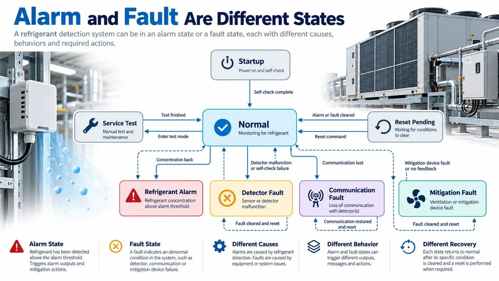
A useful equipment state model includes:
- power off;
- startup/warm-up;
- normal monitoring;
- refrigerant alarm;
- detector fault;
- communication fault;
- mitigation fault;
- service/test mode;
- reset pending.
Define transitions for simultaneous conditions. What if an alarm is active and communication then fails? What if the detector reports an internal fault while concentration is above threshold? The safest system response may preserve alarm mitigation, but the exact rule must come from the equipment safety design.
Use independent indicators or codes where practical. A technician should not clear an alarm believing it was only a communication issue. Remote telemetry should transmit both the current state and latched history.
8. Define fail-safe behavior at system level
“Fail safe” is not a property of a single output polarity. It is the behavior of the whole equipment under a defined failure. A normally energized relay can reveal some power failures, but it may create nuisance trips or behave differently during controller resets. A digital bus can provide rich diagnostics but still needs a deterministic timeout response.
The safety analysis should state the required response to:
- detector fault;
- loss of detector power;
- communication loss;
- controller reset;
- actuator failure;
- unavailable mitigation power;
- multiple simultaneous faults.
Possible actions include inhibiting compressor operation, commanding ventilation, disabling ignition sources, annunciating a service condition, or restricting equipment operation. The correct action is project- and requirement-specific; do not publish a universal sequence without the applicable context.
Test that the selected response is achievable under the same failure. If the detector and mitigation fan share a failed power supply, commanding the fan is not a sufficient fallback.
9. Specify latching, reset, and recovery
Alarm and fault recovery should prevent cycling or premature return to normal. Document:
- whether the state latches;
- minimum hold time if any;
- concentration or health criteria for clearing;
- manual or automatic reset authority;
- required number of valid samples;
- behavior after power cycle;
- remote reset permission;
- service log retention;
- restart sequence for compressors, heaters, and fans.
Hysteresis can prevent chatter, but excessive persistence can delay a necessary response or hide intermittent failures. Treat all timers and thresholds as controlled safety parameters.
After a fault clears, require a defined period of valid monitoring before enabling normal operation if the safety analysis calls for it. A communication link that reconnects for one frame should not automatically restore equipment.
10. Make the interface unambiguous
The interface control document should define every state at the electrical and protocol levels.
For RS485 or UART, include:
- baud rate, framing, address, byte order, and register map;
- update and polling intervals;
- CRC/checksum behavior;
- alarm and fault codes;
- validity and warm-up flags;
- timeout and retry policy;
- sequence/freshness method;
- startup default values;
- behavior during firmware update;
- configuration write protection.
For PWM, define frequency, duty-cycle mapping, invalid ranges, missing-pulse timeout, and startup behavior. For analog outputs, define valid measurement range, fault bands, source impedance, load, tolerance, filtering, and open/short interpretation. For discrete outputs, define energized state, contact ratings, fault supervision, and whether alarm and fault have separate lines.
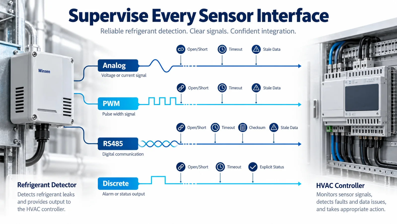
Verify the implemented software against the released interface document. Protocol misunderstandings are common when one team treats a register as instantaneous concentration while another treats it as a filtered state.
11. Connect detector diagnostics to actuator proof
A detector self-test does not prove mitigation. The equipment controller should monitor the parts of the action chain that matter to the safety concept:
- relay or contactor state;
- fan drive run/fault status;
- motor current;
- airflow or pressure switch;
- damper end switch or analog position;
- valve position feedback;
- commanded versus measured state;
- timeout to achieve the state.
Name this condition mitigation fault rather than detector fault. That preserves troubleshooting clarity. The required fallback—additional annunciation, equipment lockout, or another action—should be defined in the safety requirements.
Where periodic actuator exercise is permitted, schedule it without creating unsafe equipment operation. Some components cannot be exercised during occupancy or heating. If exercise is not feasible, define inspection and functional-test intervals.
12. Distinguish electronic self-test from a gas challenge
An electronic self-test may cover processor, optical, output, and communication functions but leave the external gas path untested. A functional gas challenge can check gas access and response, but only when it uses an approved medium and controlled method.
Do not use arbitrary aerosol, lighter gas, solvent, or household chemical as a “test.” Such substances can produce misleading responses, contaminate the detector, create a fire risk, or damage materials. Follow the current sensor and equipment instructions.
If a gas challenge is part of commissioning or maintenance, define:
- approved gas or test medium;
- concentration and tolerance;
- delivery fixture and flow;
- application point and duration;
- ambient constraints;
- pass/fail threshold and maximum time;
- recovery and ventilation method;
- logging and calibration requirements;
- personnel safety controls.
The reference delivery system has its own delay and uncertainty. Characterize it so the detector is not blamed for a long tube or an uncontrolled bag volume.
13. Validate diagnostics with fault injection
Reviewing code is not enough. Inject faults into production-representative hardware and confirm detection, signaling, timing, system response, annunciation, and recovery.
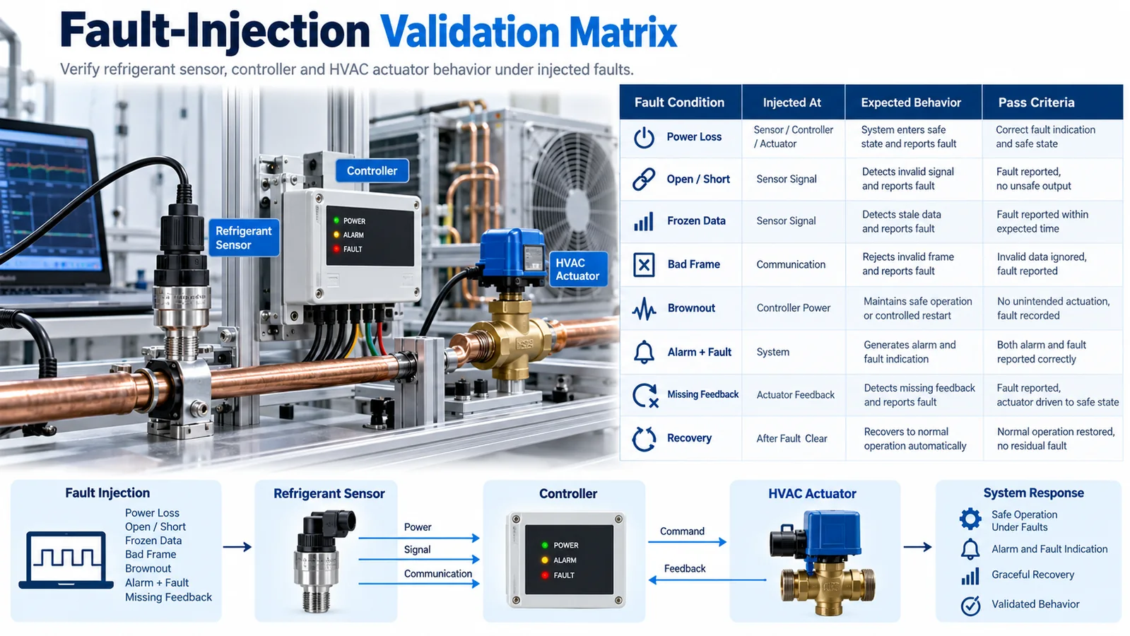
Recommended cases include:
- detector power removed and restored;
- signal wire open, shorted, and crossed;
- frozen last-valid digital frame;
- bad CRC/checksum and wrong address;
- intermittent connector contact;
- supply undervoltage and brownout;
- detector internal-fault simulation supported by the product;
- warm-up timeout;
- controller reset while detector remains powered;
- detector reset while controller remains powered;
- alarm followed by communication failure;
- actuator command with missing proof;
- service-test mode abandoned or timed out;
- restored communication with stale cached data.
Record the exact injection, timestamped state transitions, output commands, physical feedback, indicator behavior, event logs, and reset path. Repeat cases at operating extremes if timing or electrical thresholds can change.
14. Protect service and test modes
Service mode can temporarily suppress alarms, simulate outputs, or allow component replacement. That capability needs controls:
- authorized access;
- clear local and remote indication;
- automatic timeout;
- event logging;
- restrictions on compressor/heater operation;
- explicit exit and revalidation;
- no persistence after an unintended power cycle unless required and visible.
Never let a test flag remain silently active. A simulated alarm should be identifiable as a test event in logs while still proving the intended downstream sequence. If the test bypasses sensor filtering or other stages, documentation must say which portions were not exercised.
Replacement instructions should require the approved detector model and configuration. If field addressing, calibration, or parameter loading is needed, verify it before enabling normal equipment operation.
15. Control diagnostic configuration and firmware
Thresholds, filters, fault limits, timeout intervals, and protocol behavior can change through firmware or configuration. Treat them as released engineering parameters.
Maintain:
- detector hardware and firmware revision;
- controller software revision;
- configuration checksum or version;
- interface-control document revision;
- diagnostic coverage analysis;
- fault-injection results;
- known limitations and service actions;
- approval record for updates.
Engineering change control should trigger review for new sensor firmware, alternate modules, modified filtering, protocol changes, new gateways, changed power supplies, harness changes, and actuator substitutions. Targeted regression tests should be based on the affected diagnostic paths.
Secure update and configuration mechanisms against unintended changes. The cybersecurity design should not prevent the required safety action, but unauthorized parameter changes can undermine fault detection and alarm timing.
16. Define diagnostic timing separately from alarm timing
The refrigerant-alarm response budget and the fault-detection interval answer different questions. The first measures how quickly a gas condition produces mitigation. The second measures how long the system can remain unaware that monitoring is unavailable. Record both requirements and their evidence; a fast alarm path does not excuse a communication timeout that leaves stale normal data for minutes.
Build a diagnostic timing table with the failure, injection point, detection mechanism, maximum detection interval, controller transition, annunciation and fallback action. Include worst phase alignment for periodic self-tests and polling. If retries are allowed, state how many can occur before fault declaration and why that delay is acceptable.
Measure restoration as well. A reconnecting sensor may need warm-up and several valid updates before the controller can trust it. Prevent rapid fault/normal chattering by using controlled recovery logic without hiding intermittent wiring.
17. Review diagnostic independence and common-cause failures
A watchdog powered by the same failed rail it monitors may not signal externally. A controller and detector sharing one supply can reset together and lose the event history. A communication gateway can become a single point that makes several healthy sensors appear unavailable.
For each diagnostic, identify its dependencies and whether a failure can prevent the diagnostic signal. Use supervised output states, independent controller timeouts, nonvolatile logs or separate feedback where justified. Analyze shared connectors, power converters, ground references, firmware libraries and network segments as common causes.
Independence does not always require duplicate hardware, but it requires an honest architectural argument. The system should not credit two checks as independent when both depend on the same ADC, task or message.
18. Design useful service information without exposing unsafe controls
Service displays and logs should provide state, fault category, first-occurrence time, reset count, communication statistics and relevant environmental or supply information where available. Use plain descriptions in addition to numeric codes. Preserve the original fault even if a later consequence, such as missing actuator feedback, also appears.
Protect calibration, thresholds, timeout and safety-sequence parameters from unauthorized changes. A service technician may need read access without write access. If a test command can simulate alarm, require deliberate authorization, display a persistent test indication and enforce an automatic timeout.
Remote diagnostics can help, but the protective action must not depend on cloud availability. Define data privacy, cybersecurity, clock synchronization and log-retention behavior separately from the local safety response.
19. Product integration example: ZRT512E
The Winsen ZRT512E is one candidate NDIR module for R32 and R454B refrigerant-detection development. The verified local product matrix identifies an RS485 interface. The equipment manufacturer should obtain and control the current data sheet and protocol document, then confirm the exact diagnostic registers, startup states, validity flags, timeout behavior, response characteristics, and ordered hardware revision.

Do not infer certification or system-level compliance from a product image or family description. The final equipment must validate the detector, communication, controller, mitigation, diagnostics, and installation as an integrated system under the applicable requirements.
Engineering release checklist
Before release, confirm:
- The safety objectives and fault-detection interval are defined.
- Diagnostic responsibility is assigned for detector, wiring, controller, network, power, and actuators.
- Every self-test states what it proves and what it does not prove.
- Startup, warm-up, valid-data, alarm, fault, and service states are unambiguous.
- Stale and frozen data are detected.
- Open, short, power-loss, brownout, and reset behavior are tested.
- Alarm and fault remain distinguishable.
- Fail-safe behavior is defined at system level.
- Latching, reset, and recovery prevent premature restart.
- Interface mappings and timeouts match released software.
- Mitigation has appropriate physical feedback.
- Functional gas testing, if required, uses an approved controlled method.
- Fault injection covers simultaneous and recovery cases.
- Service mode is visible, logged, and time limited.
- Firmware and diagnostic configuration are under change control.
முடிவு
Self-test is not a single button and fault signaling is not a spare status bit. A reliable refrigerant-detection system combines internal diagnostics, supervised interfaces, freshness monitoring, explicit controller states, actuator proof, service controls, and fault-injection evidence. It also states honestly what electronic diagnostics cannot prove—especially external gas access and retained sensitivity.
When alarm, fault, stale data, startup, and mitigation-failure states are designed together, the HVAC controller can make deterministic decisions and service teams can diagnose the real problem. For integration support, provide Winsen with the target refrigerant, detector model, interface, controller architecture, required diagnostic interval, intended alarm/fault actions, environmental range, and applicable equipment requirements.
குறிப்புகள்
- UL Solutions: Refrigerant Detection Systems
- UL தீர்வுகள்: குளிர்பதன கண்டறிதல் அமைப்புகளுக்கான புதுப்பிக்கப்பட்ட தேவைகள்
- UL தீர்வுகள்: HVAC அமைப்புகளில் சென்சார் பதில்
- UL தீர்வுகள்: HVAC உபகரணங்களில் குளிர்பதன கண்டறிதல் அமைப்புகளை ஆய்வு செய்தல்
- AHRI எரியக்கூடிய குளிர்பதனப் பொருட்கள் ஆராய்ச்சி முயற்சி
- வின்சென் குளிர்பதன சென்சார் தீர்வு
