
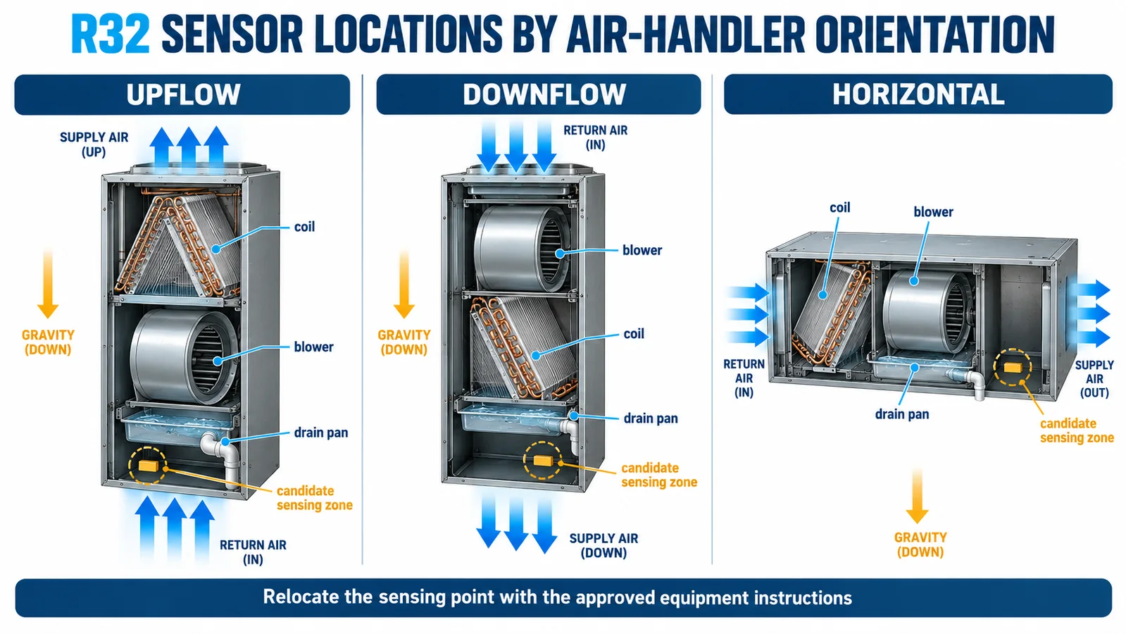
A convertible air handler may use one cabinet for upflow, downflow, horizontal-left and horizontal-right installation. The sheet metal may be shared, but the refrigerant detector does not necessarily keep the same functional location. Rotating the unit changes the physical low region, coil and pan relationship, water paths, airflow direction, service access and the route from a credible leak to the sensor inlet.
This guide gives HVAC mechanical and safety engineers a controlled method for selecting and validating R32 sensor locations by orientation. It does not provide a universal mounting coordinate or replace the evaluated equipment instructions. Final location, alarm criteria, mitigation and service rules belong to the certified equipment design.
Start with the approved equipment configurations
List every configuration that will appear on the nameplate or in the installation instructions. Separate upflow, downflow, horizontal-left and horizontal-right, even when two positions look like mirror images. Record coil size, cabinet width, blower option, electric heat, refrigerant charge, drain kit, secondary pan, filter arrangement and supported accessories.
Create one controlled drawing for each configuration. The drawing should identify the sensor bracket, inlet direction, connector, harness clips, allowable cable bend, service-removal path and nearby refrigerant joints. A single note such as “mount low” cannot control production or field conversion.
| Configuration | Geometry that changes | Placement evidence to retain |
|---|---|---|
| Upflow | return section, blower and coil stacked vertically | release path and airflow-state tests |
| Downflow | gravity-relative order and condensate path | dedicated bracket and overflow review |
| Horizontal-left | primary/secondary pan and left-side access | left-orientation release matrix |
| Horizontal-right | mirrored pan, harness and service side | right-orientation release matrix |
Map credible release sources before choosing a point
Mark field joints, distributors, headers, return bends and other refrigerant-bearing features on the production model. For each source, define the initial release direction, nearby impingement surfaces, enclosure gaps and expected equipment state. A release may start as a directional jet, cool surrounding air and entrain cabinet air before gravity and fan flow dominate its path.
Do not select a location only because refrigerant vapor can be denser than air under common conditions. The detector must intercept the concentration field in the actual cabinet, through the required range of charge, release condition, temperature and airflow. Use engineering analysis to eliminate poor zones, then qualify the remaining candidates with controlled releases.
Upflow: find a dry path with repeatable gas access
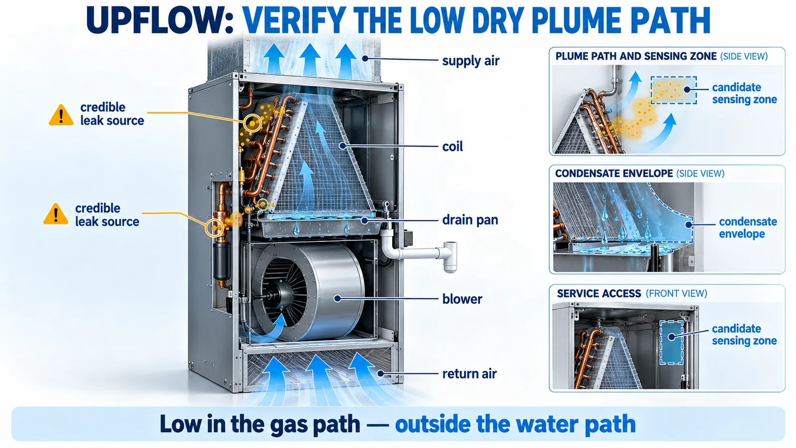
In an upflow unit, return air normally enters below the blower and conditioned air leaves above the coil. Candidate locations often appear near low cabinet regions or along a route from the coil compartment toward the return section, but the final position depends on the unit’s internal partitions and the mitigation design.
Check whether the blower moves gas toward or away from the inlet in every relevant state. Review bypass gaps around the coil, drain-pan lips, filter pressure drop, blower-off stagnation and the effect of the service panel. The inlet should remain open to cabinet air without sitting in normal condensate, a likely overflow path or a cleaning-spray target.
Downflow: re-map the physical low region
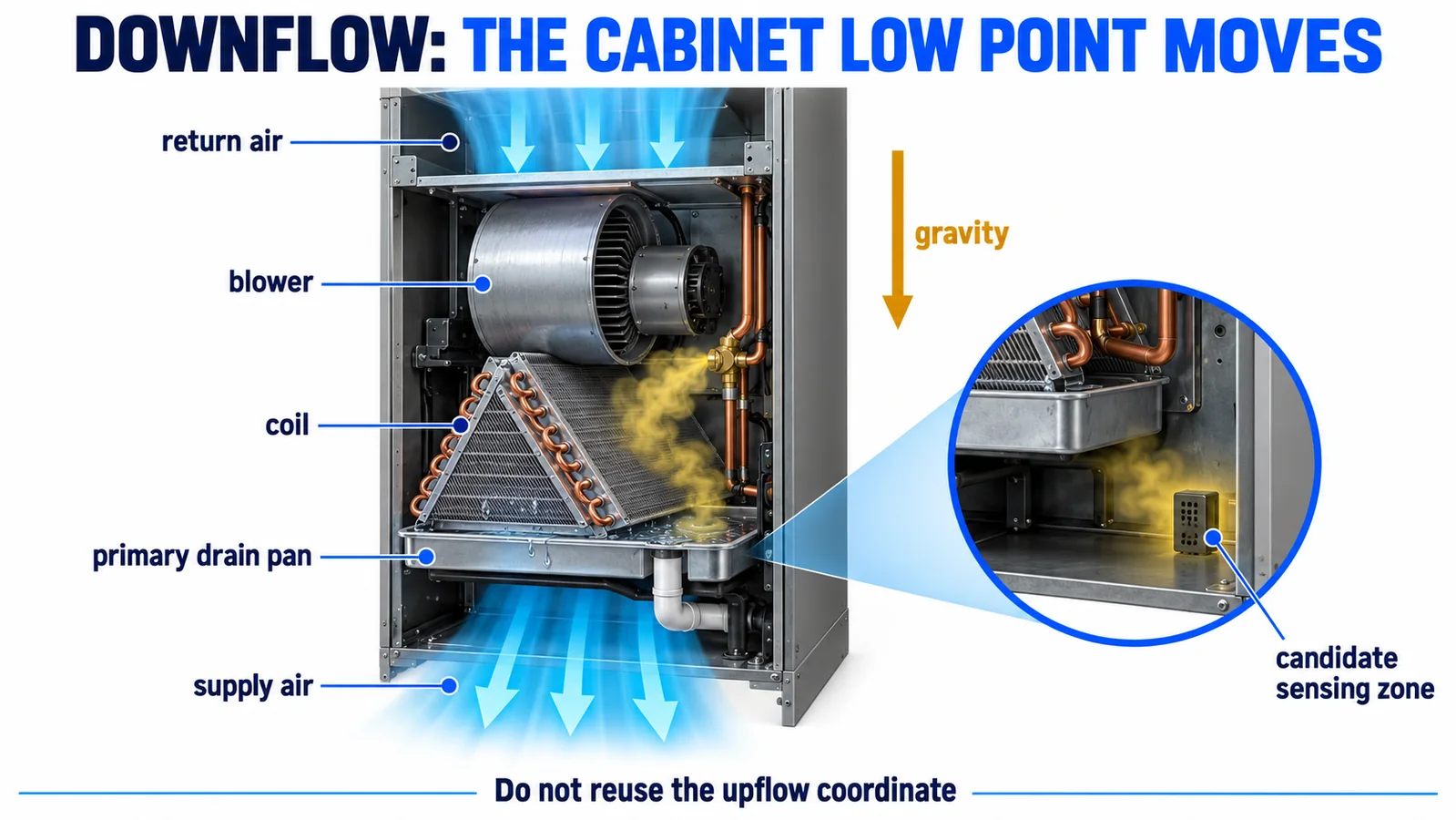
Downflow is not an upflow drawing turned upside down. The coil, blower, controls and drain assembly occupy different gravity-relative positions, and a bracket that was dry may move below the pan or into an overflow route. The supply opening can also become the lowest large boundary in the cabinet.
Start the placement study again from the downflow assembly. Confirm the approved drain conversion, pan and insulation parts, heat-kit location, harness retention and service access. If the equipment design requires a relocated detector, make the change unmistakable in the bill of material and instructions. Prevent the original bracket from remaining as an apparently valid alternative.
Horizontal-left and horizontal-right are separate cases
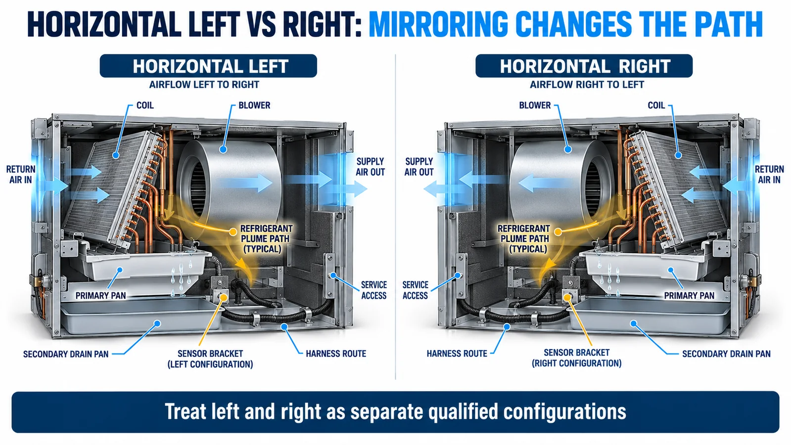
Horizontal conversion changes both the gravity vector relative to the coil and the direction of the air path through the cabinet. Left and right configurations can mirror the coil and blower while retaining non-mirrored controls, tubing, drain connections and access panels. Those asymmetries can change plume transport and water exposure.
Evaluate the primary and secondary drain pans, the lower coil corner, tubing exits, harness routing and sensor-service clearance in each direction. A longer cable that permits both positions needs controlled clips and strain relief so field routing cannot block the inlet or touch wet surfaces.
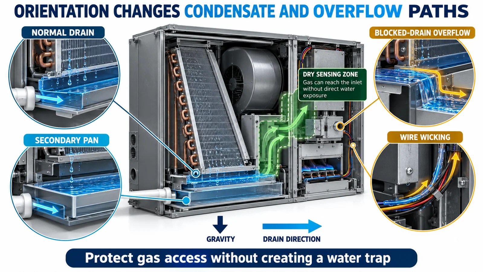
Keep the inlet available without creating a water problem
The sensing path needs cabinet air exchange, but condensate can damage the assembly, block openings or create nuisance behavior. Review normal drainage, startup carryover, blocked-drain overflow, secondary-pan filling, coil-cleaning procedures and water wicking along the cable. Include transport and installation tilt where relevant.
A shield or cover may improve water protection but can also slow gas transport. Qualify the final production enclosure, inlet orientation and mounting clearance rather than relying on the bare sensor response. Confirm that insulation cannot relax over the inlet and that sheet-metal tolerances do not pinch the gas path.
Control the field-conversion process
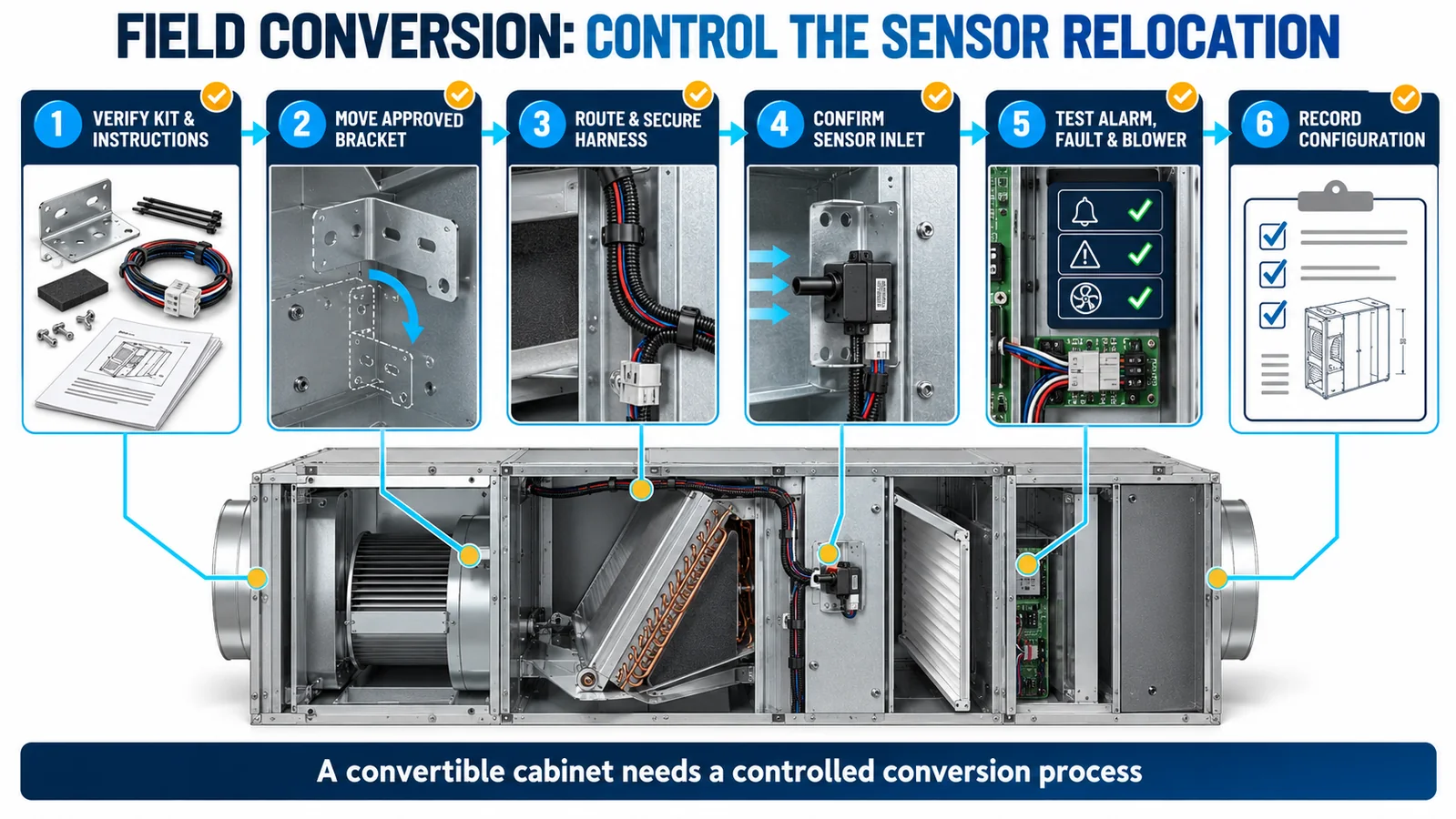
A field conversion should be a defined operation, not an installer interpretation. Supply the correct bracket or approved mounting features, orientation-specific diagrams, harness clips and functional-test instructions. Use keyed features, labels or hardware differences where practical to prevent the wrong location.
The conversion record should identify the final orientation, sensor part, bracket position, harness route and controller configuration. After conversion, verify the detector channel, diagnostic path and required equipment response with the manufacturer-approved method. Never instruct the installer to create an uncontrolled refrigerant release.
Define mechanical acceptance criteria
Release drawings should specify what production and service personnel can inspect. Useful criteria include bracket part and revision, fastener presence, sensor orientation, minimum unobstructed inlet space, connector lock, harness clipping, separation from sharp edges and drainage surfaces, and service access with the panel removed.
Include tolerance-stack review. A candidate point may work in a prototype but become shielded when insulation, pan, coil frame and cable positions reach production limits. Review alternate suppliers and service parts that can change geometry around the inlet.
Validate every orientation and operating state
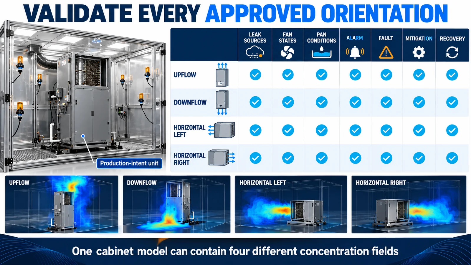
Use production-intent cabinets, coils, pans, covers, insulation, filters, harnesses and firmware. Conduct controlled releases at credible sources in each approved orientation. Include blower off, startup, normal airflow, relevant low and high airflow states, and fault conditions defined by the equipment safety concept.
Measure a reference concentration close enough to interpret the installed sensor response without disturbing the plume. Record detector output, alarm state, mitigation commands, airflow feedback and recovery. Repeat the slowest or most variable cases across environmental and manufacturing corners. The validation report should trace each tested configuration to the released drawing and software revision.
Revalidate changes that alter the concentration field
Treat changes to the coil, pan, insulation, cabinet seam, blower, filter, heat kit, wiring bundle, sensor cover or bracket as potential placement changes. Apply a documented impact review. Testing can be focused when evidence shows the change cannot affect the critical path, but that conclusion should be recorded rather than assumed.
Field feedback also matters. Water marks, damaged connectors, displaced harnesses and orientation-specific service reports can reveal gaps in the original assumptions. Link confirmed findings to drawings, instructions, end-of-line checks and the qualification matrix.
Match the sensor to the controlled interface
Winsen’s MH-Z1542B-R32 NDIR refrigerant sensor is listed in the official product export for R32 detection with an NDIR principle and UART output. The website also lists product-level performance and environmental data, but the current controlled datasheet must be used to confirm the exact variant, electrical limits, protocol, response behavior, dimensions and qualification evidence for an equipment program.

For related design work, see R32 placement in ducted air handlersஅருவடிக்கு drain-pan, blower and return-air tradeoffsஅருவடிக்கு furnace-and-coil integration மற்றும் R32 leak-alarm control sequencing.
What to send for an engineering review
Provide the refrigerant and charge, air-handler model, cabinet and coil drawings, every approved orientation, credible release points, drain and secondary-pan design, airflow range, sensor interface, alarm target, environment, annual volume and certification market. Winsen can review the sensing architecture, interface questions and orientation-specific validation matrix.
Contact Winsen for an R32 air-handler orientation review.
References
- UL Solutions: Inspecting Refrigerant Detection Systems in HVAC Equipment
- UL Solutions: Updated Requirements for Refrigerant Detection Systems
- UL Solutions: Sensor Response in HVAC Systems
- AHRI Flammable Refrigerants Research Initiative
- AHRTI 9009: Leak Detection of A2L Refrigerants in HVACR Equipment
- Daikin AMST R-32 Air Handler Installation and Operating Instructions
