
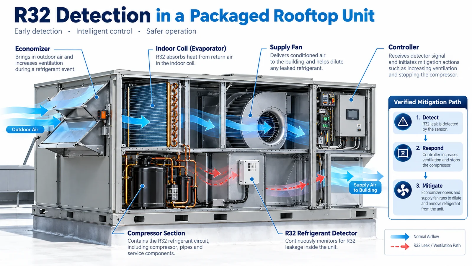
Packaged rooftop units concentrate an entire refrigeration system, air-moving system, economizer, heating section, electrical controls, and weather enclosure into one cabinet. That compact architecture makes R32 refrigerant detection a system-integration problem rather than a simple mounting task. A detector must encounter a credible release early enough in the relevant operating states, survive the rooftop environment, communicate a trustworthy alarm or fault, and trigger the mitigation sequence defined for the equipment.
The most common design error is choosing a location from a cabinet drawing while assuming that all compartments share the same air. They often do not. Compressors, coils, supply fans, outdoor-air paths, return plenums, filter sections, and electrical spaces can be separated by bulkheads and pressure differences. Economizer dampers can reverse or redirect flow. Rain, condensate, wash water, dust, heat, vibration, and service activity can challenge a detector that would perform well on a laboratory bench.
This guide provides an engineering method for R32 sensor rooftop unit integration. It does not prescribe a universal location or replace the applicable equipment standard, listing, installation instructions, or authority-having-jurisdiction requirements. The correct outcome is a traceable design supported by release-path analysis, operating-state tests, controls validation, and environmental qualification.
1. Freeze the product configuration before deciding coverage
An RTU platform may support many combinations under one model family. Detector coverage must be evaluated for the actual configurations, not only for a representative cabinet.
Document at least:
- refrigerant and maximum charge by circuit;
- number of independent refrigeration circuits;
- compressor and coil arrangement;
- cabinet size and compartment partitions;
- supply-fan type and location;
- draw-through or blow-through airflow arrangement;
- economizer option and damper geometry;
- return-air and outdoor-air opening locations;
- gas heat, electric heat, or heat-pump options;
- heat-recovery or energy-recovery accessories;
- curb, horizontal-discharge, and down-discharge configurations;
- factory and field-installed accessories;
- controller, interface, and mitigation sequence;
- detector power source and permitted startup behavior.
Create a variant matrix. A sensor position that covers a single-circuit, downflow cooling unit may not cover a two-circuit heat pump with a different fan, economizer, and horizontal discharge. If the platform contains major airflow architectures, group them into qualification families only when the equivalence is supported by geometry and test evidence.
2. Map compartments as separate gas-control volumes
Start with a cabinet cutaway and mark every bulkhead, opening, cable penetration, drain, panel seam, and airflow connection. Treat each space as a potential control volume until testing proves reliable exchange with adjacent spaces.
Typical RTU zones include:
- compressor compartment;
- outdoor coil compartment;
- indoor coil or evaporator compartment;
- mixed-air/economizer section;
- filter section;
- supply-fan section;
- return plenum;
- heating section;
- electrical/control compartment;
- curb or base rail cavities.
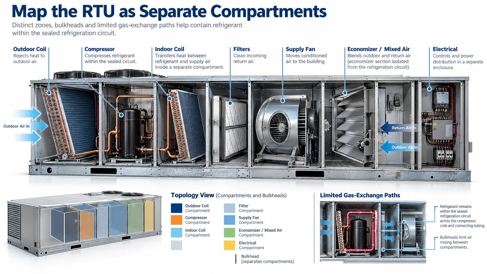
The electrical compartment is not automatically an appropriate detector location merely because power and control wiring are convenient. It may be sealed from the refrigerant circuit, positively pressurized, warm, or exposed to contactor and cleaning vapors. Conversely, a detector placed in the evaporator airflow may not see a compressor-compartment release when the unit is off.
For each partition, record whether exchange occurs by intentional airflow, leakage, convection, or not at all. Note how panel installation and field gasketing affect exchange. Temporary testing with service panels removed can create a misleading short path that disappears in production.
3. Build a credible release-source map
The release map should follow real refrigerant-bearing components:
- compressor terminals and shell connections;
- suction and discharge joints;
- reversing valve and accumulator connections;
- service valves and pressure ports;
- pressure switches and transducers;
- indoor and outdoor coil headers;
- distributor joints and capillary connections;
- filter-drier and receiver joints;
- field-installed piping interfaces;
- tubing near vibration supports or sheet-metal edges.
Rank locations by charge available, failure credibility, release direction, and separation from a candidate sensing point. Do not assume the largest component is always the most difficult case. A small joint behind a baffle can direct gas into a stagnant cavity, while a larger release in the primary airstream may reach the detector quickly.
If the unit has multiple circuits, show each circuit in a different color. Determine whether a release from either circuit reaches the same sensing zone in all required states. If not, the architecture may need multiple sensing points or a different control strategy.
4. Analyze operating states before choosing a mounting point
RTU airflow is state-dependent. A useful state matrix includes:
- occupied cooling;
- unoccupied cooling;
- heating;
- heat-pump heating;
- defrost;
- ventilation-only operation;
- economizer cooling;
- minimum outdoor-air ventilation;
- supply fan off;
- compressor off with fan on;
- startup and shutdown;
- smoke-control or emergency modes if applicable;
- service state with panels installed and removed.
For each state, mark fan status, damper position, pressure zones, active refrigeration circuit, and intended mitigation availability. The slowest detection case may occur during standby, not during rated cooling.
5. Economizer position can completely change the release path
Economizer dampers combine return air and outdoor air upstream of the indoor coil or fan. Their positions can create strong dilution, redirect a release, or isolate a compartment. Wind pressure at the outdoor-air hood can add another variable.
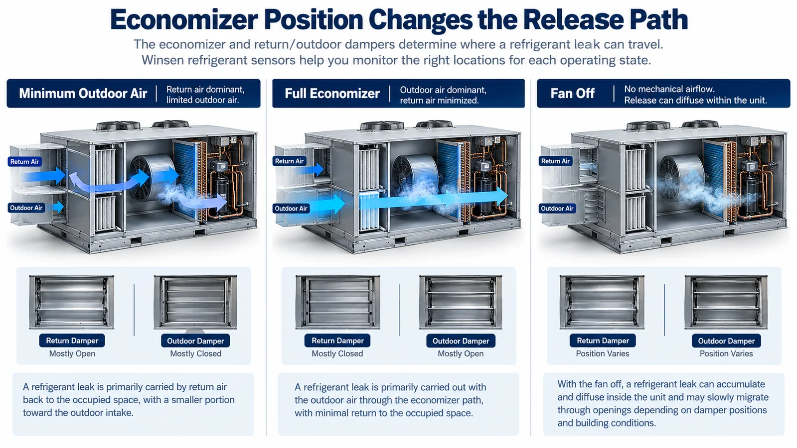
Evaluate at least:
- outdoor-air damper closed or at minimum position;
- outdoor-air damper fully open;
- return-air damper open and modulating;
- relief or exhaust path active;
- fan on and fan off;
- wind from different directions if the hood is exposed;
- failed or stuck damper positions relevant to the safety analysis.
A sensor mounted in mixed air may experience excellent transport when the fan operates but weak coverage after shutdown. A sensor in the coil compartment may respond differently when outdoor air dilutes the incoming stream. Do not use a single smoke visualization at one damper position as the whole validation.
6. Fan-on and fan-off cases need separate reasoning
During fan operation, a release can be entrained, diluted, and distributed through the duct system. The candidate detector must see enough concentration soon enough despite dilution. During fan-off conditions, the release may follow density, temperature, release momentum, and cabinet leakage into lower pockets.
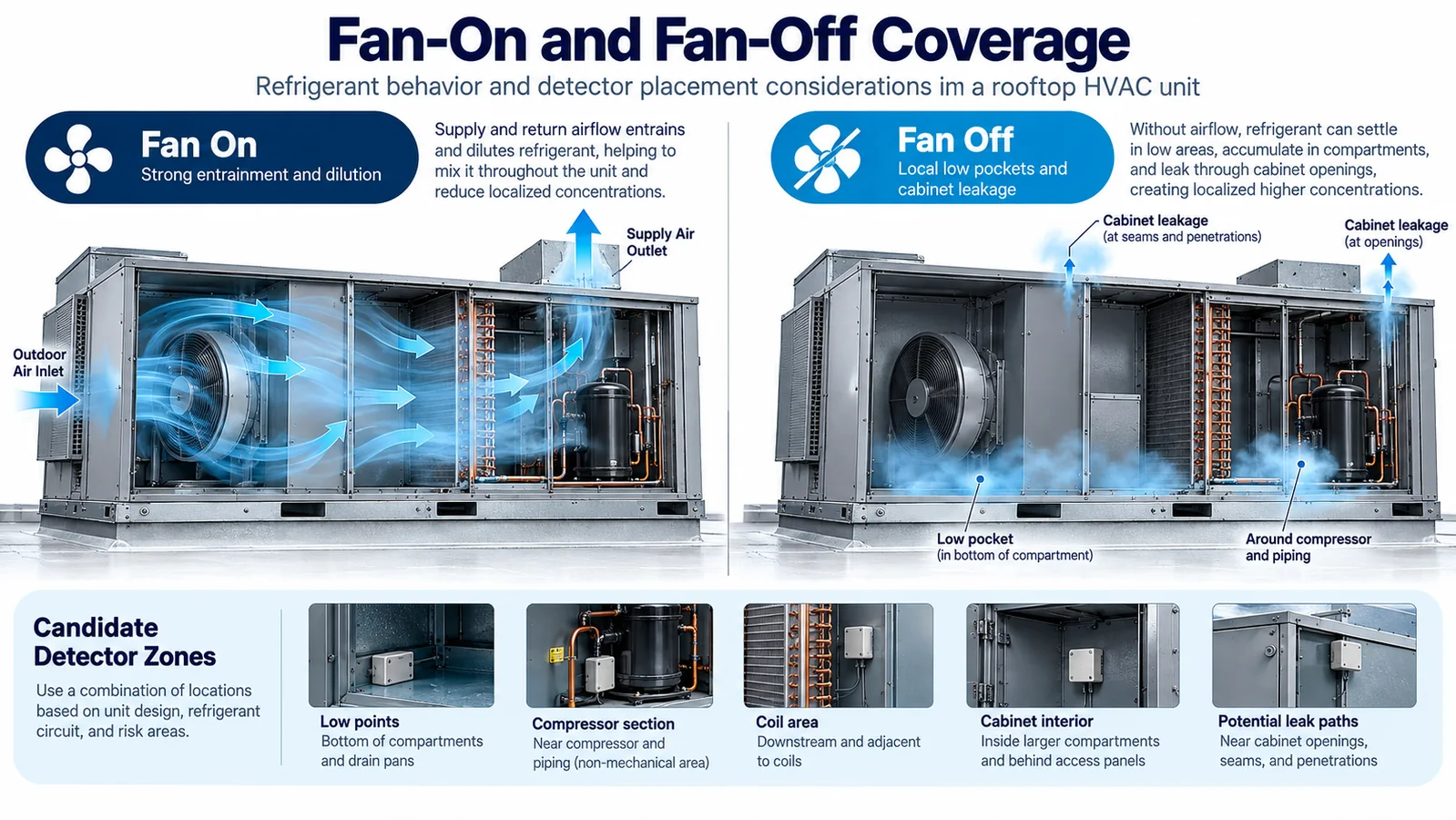
Map the following for both conditions:
- primary flow direction;
- local recirculation and bypass;
- regions behind coil frames and drain pans;
- leakage through panel seams;
- low points and base-rail cavities;
- openings into the curb or building return;
- heat sources that drive convection;
- detector inlet orientation and clearance.
It can be valid to locate a detector in an air path, but only if the required states are covered and the inlet remains protected. It can also be valid to monitor a stagnant compartment directly. The evidence, not a slogan about refrigerant density, should determine the design.
7. Keep occupied-air and outdoor-compartment questions distinct
An RTU may release refrigerant into an outdoor compressor section, into the supply-air path, or into both depending on component location. These scenarios have different consequences and transport paths. The design team should identify which zones the applicable equipment requirements expect the detection and mitigation system to address.
Do not assume that an outdoor location makes detection unnecessary, and do not assume that a detector in the supply stream covers every outdoor circuit joint. Similarly, a detector near compressors may provide rapid outdoor-compartment detection without proving detection of an indoor-coil release entering occupied air.
Use separate acceptance criteria and test records when the functions differ. This improves both engineering clarity and compliance review.
8. Protect the detector from weather without trapping gas
Rooftop equipment faces rain, wind-driven moisture, snow, ice, dust, insects, UV exposure near openings, high solar temperature, condensation, coil-cleaning chemicals, and pressure washing. A protective cover must balance environmental protection with gas access.
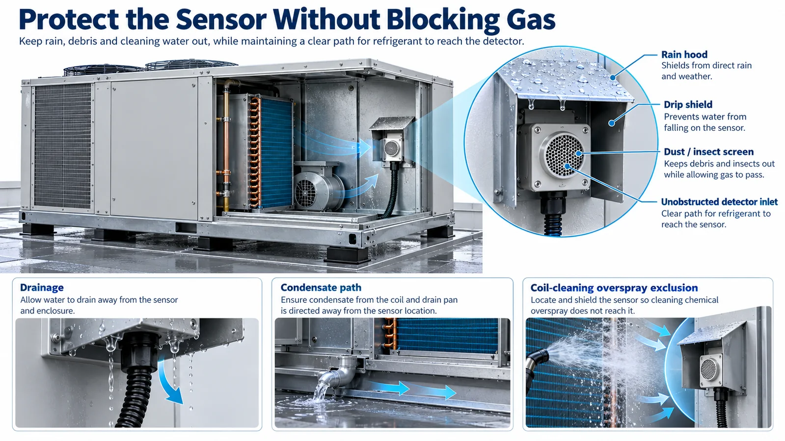
Good integration questions include:
- Can rain or condensate run directly into the inlet?
- Can water collect in a cup or downward-facing pocket?
- Will a membrane remain wet and delay gas exchange?
- Can dust or insects block the opening?
- Is the detector exposed to coil-cleaning overspray?
- Is the operating temperature within the controlled sensor specification?
- Will service washing direct high-pressure water at the detector?
- Can the harness wick water into the enclosure?
- Does the cover preserve the qualified inlet area and clearance?
Use drip shields, drainage, orientation, and suitable materials where needed, but test the final assembly. A weather shield added after response testing can invalidate the original timing result.
9. Account for condensate and drain-pan geometry
The indoor coil section contains water during normal operation. Drain pans, traps, and sloped floors create obstructions and possible low pockets. Condensate droplets or splash can reach a nearby detector; microbial treatment or cleaning products can create chemical exposures.
Keep the detector away from direct splash and drain-treatment application while maintaining a representative gas path. Confirm that a blocked drain or sloshing during transport does not flood the inlet. If a cover is used, prove both drainage and response time after wetting or high-humidity exposure as required by the qualification plan.
10. Separate the detector power and signal design from convenience wiring
Detector behavior during power transitions matters. Document:
- supply range and tolerance at the detector;
- startup and warm-up state;
- brownout behavior;
- current demand and wiring voltage drop;
- grounding and EMC design;
- connector keying and retention;
- reverse-polarity or miswire protection;
- alarm, fault, and communication states;
- maximum data age;
- controller response during detector reset.
Do not power the detector from an output that shuts off in the very modes when monitoring is required. If the controller or fan drive generates electrical noise, validate the integrated harness routing and grounding, not only the sensor on a clean bench supply.
For field service, use connectors and diagnostics that reduce the chance of leaving the detector disconnected. A disconnected detector should become an explicit fault within the required diagnostic interval rather than silently appearing normal.
11. Define a complete control sequence
The control sequence begins with valid detector data and ends with verified mitigation or a defined fault response. It should specify:
- normal, warm-up, alarm, fault, and stale-data states;
- threshold ownership and configuration control;
- any persistence or debounce;
- required fan and damper commands;
- compressor, heater, valve, or ignition interlocks where applicable;
- local and remote annunciation;
- alarm latching and reset authority;
- behavior after power interruption;
- actuator proof and timeout;
- response if mitigation fails.
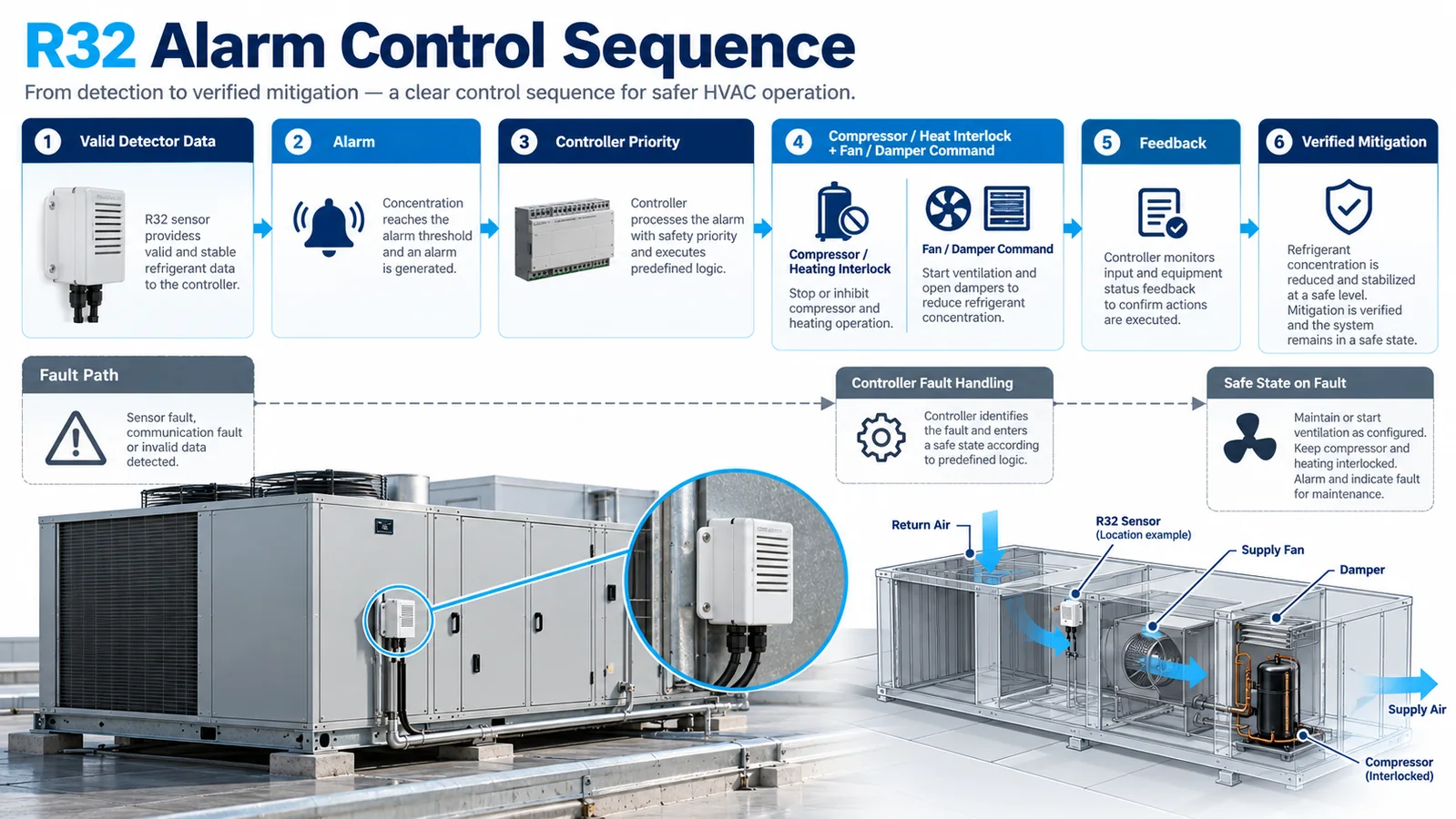
Economizer and ventilation controls may normally prioritize energy or indoor-air-quality objectives. The refrigerant safety sequence must have defined priority when those objectives conflict. Document which controller owns the final command and how overrides are released.
If heating components are present, analyze the interaction between refrigerant alarm and heat. Electric elements, gas ignition, hot surfaces, and blower delays may affect the required sequence. Do not copy a cooling-only sequence into a heat-pump or gas/electric unit without review.
12. Measure the full response, not just the sensor output
Use a synchronized acquisition method to record:
- release initiation;
- reference concentration near the detector inlet;
- detector output or state;
- controller recognition;
- relay or network command;
- fan, damper, or valve feedback;
- airflow or other physical result.
The sensor response time is only one part of the total. Gas transport through the cabinet may dominate in fan-off states, while damper travel or fan ramp may dominate mitigation. Test the final enclosure, production controller, actual harness, and representative actuator.
13. Build a validation matrix around worst cases
The validation matrix should cross release location, operating state, damper position, fan status, unit variant, environmental condition, and detector fault cases.
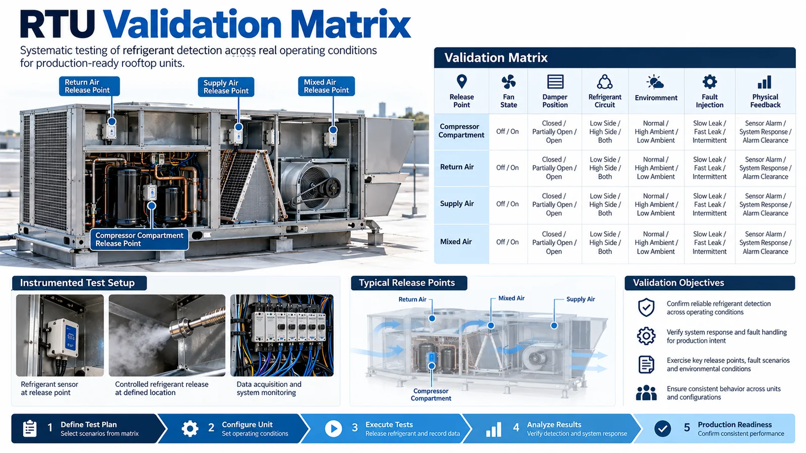
Recommended test families include:
- Transport visualization — identify likely paths and stagnant zones.
- Calibrated concentration testing — measure concentration history at the detector.
- Integrated response timing — release to physical mitigation.
- Environmental exposure — temperature, humidity, condensation, water, dust, vibration, and chemicals as applicable.
- Electrical robustness — voltage tolerance, transients, EMC, and communication recovery.
- Fault injection — disconnected sensor, stale data, failed actuator, and power interruption.
- Production variation — cabinet, fan, damper, charge, and assembly tolerances.
Use multiple trials and preserve raw data. Record panel state, damper command and actual position, fan speed, wind condition, ambient temperature, release method, refrigerant or surrogate basis, and sensor/firmware revision.
14. Design commissioning and service into the product
The installed RTU needs practical checks that do not encourage unsafe refrigerant release. Commissioning should verify:
- correct detector part and revision;
- mounting location, orientation, and inlet clearance;
- harness routing and connector seating;
- normal, warm-up, alarm-test, and fault indications;
- controller mapping and remote annunciation;
- fan/damper/valve output action;
- required feedback;
- reset procedure;
- service access after panels are installed.
Electronic self-test can check parts of the internal circuit and communication path, but it may not prove gas transport or sensitivity. If the product instructions call for a controlled functional or gas challenge, define the approved method, test medium, concentration, delivery fixture, and pass criteria.
Place service labels where technicians can see them. Protect the detector from being used as a handhold, covered by insulation, or sprayed during cleaning. Replacement instructions must require the exact approved configuration or a validated equivalent.
15. Control platform and supplier changes
RTUs evolve through alternate fans, coils, controllers, panels, dampers, harnesses, and refrigerant circuit changes. Each can affect the detection system.
Add a refrigerant-detection impact review to engineering change control. Trigger review for:
- moved or added joints;
- charge changes;
- different compartment panels or seals;
- fan or airflow changes;
- economizer redesign;
- new detector hardware or firmware;
- inlet-cover changes;
- revised filters or alarm persistence;
- controller task or network changes;
- actuator supplier changes;
- new field-installed accessories.
Compare changes with the qualified release-path and timing evidence. Targeted regression testing may be enough for a bounded change, while a new airflow architecture may require full requalification.
16. Evaluate wind, curb, and building-pressure interactions
An RTU does not operate in a neutral laboratory. Wind across the outdoor-air hood, condenser section and relief opening can create positive or negative pressure inside compartments. The roof curb can connect the cabinet to return or supply plenums, and building pressure can reverse leakage through seams when the fan cycles.
Include the permitted curb and discharge arrangements in the analysis. Downflow, horizontal supply and field transitions may change where a release migrates after the supply fan stops. A curb adapter can create a cavity below the base rail; determine whether that space is inside the evaluated gas path and whether inspection or sealing is required.
Use wind testing or a technically justified range when outdoor openings materially affect coverage. Record direction and speed, damper position, relief operation and fan status. Avoid claiming a universal rooftop result from a sheltered test with all panels open.
17. Address multiple circuits and staged operation
Many packaged units stage compressors or use independent tandem circuits. Map each circuit with its available charge, coil section, joints and valves. Then test the operating combinations that can create different transport: first stage only, second stage only, both stages, one circuit locked out, and transitions between stages.
If one detector is proposed for several circuits, demonstrate that each release reaches it under the weakest relevant airflow. A shared supply fan does not automatically create a shared path when coil frames, drain pans or compressor partitions separate sources. Preserve circuit identity in service records so an alarm investigation can be linked to the active stage and pressure history.
18. Coordinate refrigerant detection with smoke and fire controls
RTUs may receive smoke-detector, fire-alarm, emergency ventilation or building-pressure commands. Those functions can stop fans or close dampers while the refrigerant sequence requests ventilation. Define priority and the permitted combined state through the applicable equipment and building safety requirements; do not let separate software teams create contradictory overrides.
Test coincident inputs in the controller or hardware-in-loop environment. Confirm what is annunciated, which command wins, whether the detector remains powered, and how the unit recovers after one condition clears. Document interfaces to the building automation system as monitoring or command authority, rather than assuming a network point can control a listed safety function.
19. Create production and field acceptance tests
Production should verify the detector part, bracket, inlet clearance, harness routing, connector, address or configuration, controller mapping, alarm/fault signal and required output sequence. Where a full gas release is impractical, use approved electrical or functional tests to cover the intended stages and rely on controlled type-test evidence for transport.
Field acceptance should confirm panels, curb, ducts, economizer, dampers, filters and accessories match an approved configuration. Verify detector warm-up and health, remote annunciation, actuator feedback and reset behavior. Record the unit serial, detector revision and controller software so a later service event can be reconstructed.
Neither test should overclaim coverage. An electronic alarm simulation proves the downstream control path; it does not prove gas can reach the installed inlet. State that limitation in the procedure.
20. Review service scenarios with panels and power states
Service work changes the cabinet. A removed access panel can eliminate a stagnant pocket or expose the detector to outdoor wind, while a technician may disable the supply fan, economizer or compressor. Define whether refrigerant monitoring remains active during approved service modes and how loss of monitoring is indicated.
Map common tasks such as gauge connection, refrigerant recovery, brazing, coil cleaning, filter replacement, belt or motor service, economizer adjustment and controller replacement. Identify which tasks can expose the detector to concentrated refrigerant, cleaning chemical, water, smoke or electrical transients. Instructions should specify isolation, ventilation, detector protection and the post-service functional checks without encouraging unsafe intentional release.
After panels are restored, verify seals, detector inlet clearance, harness connection, damper linkage and feedback. A panel screw or insulation blanket can alter the qualified gas path. If the controller or detector was replaced, confirm address, firmware, refrigerant configuration, alarm mapping and event logging before returning the RTU to automatic operation.
21. Preserve traceability across OEM and field data
Link the RTU serial number to detector model and revision, controller software, economizer option, circuit configuration and production test result. For field events, collect operating state, damper position, fan command and feedback, ambient condition, alarm/fault history and service changes. This information distinguishes a gas-transport issue from a wiring, power or actuator problem.
Trend response and fault categories across cabinet sizes and suppliers. A cluster associated with one foam seal, panel tool or damper actuator can reveal a production change before it becomes widespread. Feed the finding into the same impact-review process used for engineering changes, then update instructions and regression tests with traceable approvals.
22. Product integration example: ZRT512J
The Winsen ZRT512J is one candidate module for evaluating R32, R454B, or R290 refrigerant-detection designs. The verified local product information identifies NDIR sensing and lists PWM, RS485, and UART interface options. Before release, the OEM must confirm the exact ordered configuration, current data sheet, electrical limits, diagnostic behavior, response characteristics, environmental range, and interface protocol.

Module selection does not establish RTU system compliance. Final placement, weather protection, gas transport, controls, mitigation, equipment construction, and certification remain part of the complete product design.
Engineering release checklist
Before freezing an RTU detector design, verify:
- Every cabinet variant and circuit is in the coverage matrix.
- Compartments and gas-exchange paths are documented.
- Credible release points are mapped by circuit.
- Fan-on and fan-off transport are validated.
- Economizer and return/outdoor-air damper states are included.
- Outdoor and occupied-air functions are distinguished.
- The inlet is protected from weather, condensate, wash water, and blockage.
- Power, warm-up, brownout, communication, and stale-data behavior are defined.
- Alarm and fault states have explicit control responses.
- The required physical mitigation is measured or proven.
- Service and commissioning checks are practical and documented.
- Production and engineering changes trigger detection-system review.
Wniosek
R32 detection in a packaged rooftop unit cannot be reduced to mounting a sensor near the coil. The RTU is a collection of changing control volumes exposed to multiple airflow states and a demanding rooftop environment. Successful integration begins with configuration control, compartment and release mapping, and a state matrix. It continues through inlet and environmental design, control-sequence definition, response-time measurement, fault injection, and production change control.
When those disciplines are applied, the detector becomes a verified part of the equipment safety function rather than an isolated component. For product-selection and integration support, provide Winsen with the refrigerant, maximum charge, circuit count, cabinet cutaway, airflow and economizer states, environmental range, target interface, mitigation sequence, and applicable timing or diagnostic requirements.
Referencje
- Rozwiązania UL: Kontrola systemów wykrywania czynnika chłodniczego w urządzeniach HVAC
- Rozwiązania UL: Zaktualizowane wymagania dotyczące systemów wykrywania czynnika chłodniczego
- UL Solutions: Refrigerant Detection Systems
- Inicjatywa badawcza AHRI nad łatwopalnymi czynnikami chłodniczymi
- AHRTI 9009 Final Report
- Winsen ZRT512J product page
